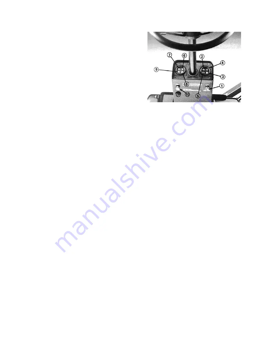
indicator light and audible signal warn of excessively high
hydraulic temperature.
Hydraulic Oil Level Warning (Fig. 8)—A warning indicator
light and audible signal warn of low hydraulic oil level. If the
oil level drops further, the engine will automatically stop. The
engine cannot be restarted until the oil supply is brought to a
safe level.
Hydraulic Oil Filter Warning (Fig. 8)—A warning indicator
light and audible signal warn of a clogged hydraulic filter.
Air Cleaner Warning (Fig. 8)-—A warning indicator light
and audible signal warn that the filter is clogged and in need
of service.
Alarm Silence Button (Fig. 8)—Pressing this button silences
the alarm. The alarm system will disengage and automatically
reset when the problem is corrected or the alarm silence but-
ton is pressed.
Speedometer (Fig. 11)—Indicates the machine’s ground
speed. Use it with the ground speed limiter and the reel speed
control to get an appropriate rate of grass clip.
Horn—In the center of the steering wheel. Operates only
when the key switch is ON.
Traction Pedal (Fig. 9)—Controls forward and reverse opera-
tion. Depress the top of the pedal to move forward and the
bottom to move backward. The ground speed depends on
how far the pedal is depressed.
•
For no load, maximum ground speed, fully press the
pedal while the throttle is in FAST.
•
For maximum power under load or when going uphill,
keep the engine rpm high by having the throttle in FAST
and the traction pedal held stationary against the ground
speed limiter. If the engine rpm begins to decrease due to
load, gradually reduce the traction pedal pressure until
the engine speed increases.
To stop, reduce foot pressure on the traction pedal and
allow it to return to the center position. On extreme
downhill slopes, apply pressure to the REVERSE side of
the pedal, or operate with your heel on REVERSE and
your toe on FORWARD part of the pedal.
Ground Speed Limiter (Fig. 9) controls the traction pedal
movement. Limiter lever helps control the rate of grass clip
and eliminates sudden speed variations over rough terrain.
Figure 8
1.
Warning light check switch
2.
Engine oil pressure warning
3.
Fuel system warning
4.
Coolant temperature warning
5.
No charge warning
6.
Hydraulic oil temperature warning
7.
Hydraulic oil level warning
8.
Hydraulic oil filter warning
9.
Air cleaner warning
10. Alarm silence button


