Toro ProCore SR Series Скачать руководство пользователя страница 84

ProCore SR Series

Page 5 -- 22

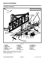
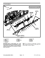
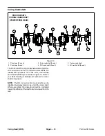
Coring Head (SR48 & SR72)

Gearbox

1. Idler shaft

2. Master link assembly (2 used)

3. Jam nut (grooved)

4. Jam nut

5. Idler sprocket

6. Lock nut

7. Sprocket hub (2 used)

8. Cap screw (4 used)

9. Sprocket (2 used)

10. Saddle bolt (10 used)

11. Lock washer (4 used)

12. Drive chain (2 used)

13. Lock nut (10 used)

14. Lock washer

15. Gearbox assembly

16. Bolt

17. Hex nut

18. PTO driveshaft

19. Square key

20. Driveshaft shield

21. Cap screw (4 used)

22. Lock washer (4 used)

23. Flat washer (4 used)

24. Cap screw (3 used per hub)

25. Cap screw (3 used per sprocket)

Figure 20

PROCORE SR72 SHOWN

3

6

8

9

10

11

13

1

7

12

15

16

17

18

19

20

4

6

5

5

4

1

3

7

9

21

22

23

24

25

14

14

14

14

24

19

25

17

16

2

2

12

FRONT

RIGHT

NOTE:

Gearbox installation for ProCore SR48 and

SR72 series aerators is very similar. The ProCore SR72

is shown in Figure 20.

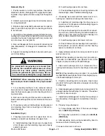
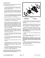
Gearbox Removal (Fig. 20)

1. Position aerator on a firm, level surface. If aerator is

attached to tractor, disengage PTO, apply tractor park-

ing brake, stop engine and remove key from the ignition

switch.

2. Remove screens from aerator frame (see Covers

Removal in the Service and Repairs section of Chapter

3 -- Chassis).

3. Drain lubricant from gearbox.

4. Disconnect PTO driveshaft from gearbox input shaft

(see PTO Driveshaft Removal in the Service and Re-

pairs section of Chapter 3 -- Chassis).

Содержание ProCore SR Series

Страница 1: ...Form No 10174SL Rev A ProCore SR Series Models SR48 SR54 SR54 S SR70 SR70 S SR72 and SR75 Original Instructions EN...

Страница 2: ...ontained herein is the sole property of The Toro Company and or its affiliated companies No intellectual property rights are granted by the delivery of this document or the disclosure of its content T...

Страница 3: ...lications To do this effectively we encourage user feedback Please comment on the completeness accuracy organization usability and readability of this manual by an e mail to servicemanuals toro com or...

Страница 4: ...NOTES _...

Страница 5: ...l Additional copies of the Operator s Manuals and Parts Catalog are avail able on the internet at www Toro com The Toro Company reserves the right to change product specifications or this publication...

Страница 6: ...ProCore SR Series This page is intentionally blank...

Страница 7: ...g Head SR54 SR70 Specifications 4 2 General Information 4 4 Special Tools 4 7 Service and Repairs 4 8 Chapter 5 Coring Head SR48 SR72 Specifications 5 2 General Information 5 4 Special Tools 5 6 Servi...

Страница 8: ...ProCore SR Series This page is intentionally blank...

Страница 9: ...ProCore SR Series Page 1 1 Safety Chapter 1 Safety Table of Contents SAFETY INSTRUCTIONS 2 Before Operating 2 While Operating 3 Maintenance and Service 3 SAFETY AND INSTRUCTION DECALS 4 Safety...

Страница 10: ...th com ply with the following safety instructions Before Operating 1 Review and understand the contents of the Opera tor s Manual before starting and operating the vehicle Become familiar with the con...

Страница 11: ...ngine and remove key from ignition switch C Wait for all moving parts to stop before leaving the tractor Maintenance and Service 1 The Operator s Manual provides information regard ing the operation g...

Страница 12: ...ety and instruction decals are affixed to the ProCore SR series deep tine aerator If any decal becomes illegible or damaged install a new decal Part numbers for replacement decals are listed in your P...

Страница 13: ...r Torque Specifications 6 Conversion Factors 6 Product Records Insert Operator s Manual and Parts Catalog for your ProCore SR Series deep tine aerator at the end of this chapter Additionally if any op...

Страница 14: ...0 09375 ProCore SR Series Page 2 2 Product Records and Maintenance Equivalents and Conversions...

Страница 15: ...rque feature hardness of the surface underneath the fastener s head or similar condition which affects the installation As noted in the following tables torque values should be reduced by 25 for lubri...

Страница 16: ...2 22 3 30 3 41 4 43 4 58 5 3 8 24 UNF 17 2 18 2 24 3 35 3 47 4 50 4 68 5 7 16 14 UNC 27 3 27 3 37 4 50 5 68 7 70 7 95 9 7 16 20 UNF 29 3 29 3 39 4 55 5 75 7 77 7 104 9 1 2 13 UNC 30 3 48 7 65 9 75 8 1...

Страница 17: ...90 10 N m 92 9 ft lb 125 12 N m M16 X 2 0 166 15 ft lb 225 20 N m 229 22 ft lb 310 30 N m M20 X 2 5 325 33 ft lb 440 45 N m 450 37 ft lb 610 50 N m NOTE Reduce torque values listed in the table above...

Страница 18: ...n lb Wheel Bolts and Lug Nuts Thread Size Recommended Torque 7 16 20 UNF Grade 5 65 10 ft lb 88 14 N m 1 2 20 UNF Grade 5 80 10 ft lb 108 14 N m M12 X 1 25 Class 8 8 80 10 ft lb 108 14 N m M12 X 1 5 C...

Страница 19: ...eshaft Clutch Service 10 PTO Driveshaft Cross and Bearing Service 12 Hydraulic Top Link 14 Covers ProCore SR54 SR54 S SR70 and SR70 S 16 Covers ProCore SR48 and SR72 18 Covers ProCore SR75 20 General...

Страница 20: ...LUBRICANT ANTISEIZE LUBRICANT 2 3 6 8 9 10 11 13 1 5 7 12 14 4 NOTE ProCore SR54 and SR 70 aerators use a single roller with two 2 bolt flange bearings Fig 1 Models SR54 S and SR70 S use two 2 roller...

Страница 21: ...sure that roller is supported as it is installed to the machine 2 Position roller with flange bearings under raised aer ator NOTE Drop speed can be adjusted on the tractor Re fer to the Tractor Opera...

Страница 22: ...ure 4 Roller Removal Fig 4 1 Position aerator on a firm level surface with aerator attached to tractor Disengage PTO apply tractor park ing brake stop engine and remove key from the ignition switch 2...

Страница 23: ...ews in bearings at this time CAUTION To prevent personal injury make sure that roller is supported as it is installed to the machine 3 Position roller with verticalroller bars and flange bea rings und...

Страница 24: ...tor to prevent it from moving 3 Chock roller to prevent it from moving 4 Loosen two 2 set screws that secure each bearing locking collar to roller shaft Fig 7 5 Remove four 4 cap screws and lock nuts...

Страница 25: ...or mation 3 Start engine on tractor Slowly lower aerator to posi tion aerator frame to roller assembly Stop tractor engine and remove key from the ignition switch 4 Align holes in flange bearings with...

Страница 26: ...to tractor disengage PTO apply tractor park ing brake stop engine and remove key from the ignition switch 2 Unhook driveshaft shield safety chains from the trac tor and the aerator driveshaft shield...

Страница 27: ...ctor PTO shaft Fig 9 A Align splines of driveshaft yoke with tractor PTO shaft and slide yoke onto shaft as far as possible B Pull back on yoke so that locking collar secures driveshaft to PTO shaft C...

Страница 28: ...hub 23 Cone shield clutch side 24 Cross and bearing kit 25 Nut 8 used 26 Connector Figure 11 PROCORE SR72 SHOWN 2 3 6 9 11 13 1 5 7 12 14 15 16 17 22 23 25 4 4 5 8 24 8 10 18 19 20 21 24 26 CAUTION Th...

Страница 29: ...ure clutch components with eight 8 cap screws item 17 springs item 15 and nuts item 25 Tighten nuts so that spring length is 1 125 28 6 mm Fig 13 3 InstallPTO driveshaftto aerator see PTODriveshaft In...

Страница 30: ...d inspect all components 5 To install new cross and bearings A Apply a coating of grease to bearing bores of end yoke and shaft yoke Also apply grease to bearings and seal of bearing assembly Make sur...

Страница 31: ...ProCore SR Series Page 3 13 Chassis This page is intentionally blank Chassis...

Страница 32: ...8 9 10 11 13 18 5 7 12 14 15 4 16 17 19 2 1 16 20 Disassembly Fig 15 1 Remove hydraulic top link from aerator and tractor Fig 16 2 Remove spacers item 16 from cylinder shaft clevis and adapter on bar...

Страница 33: ...rings back up rings and wiper with clean hydraulic oil Carefully install new back up rings O rings and wiper to head and piston IMPORTANT Do not clamp vise jaws against the shaft surface Clamp on the...

Страница 34: ...10 Cap screw 4 used 11 Screen clip 2 used 12 Flat washer 10 used 13 Lock nut 4 used 14 Cap screw 2 used 15 Socket head screw 4 used 16 Lock nut 4 used PROCORE SR54 SHOWN FRONT RIGHT 2 3 6 8 9 10 11 13...

Страница 35: ...1 D Remove cap screw lock washer and flat washer that secure front screen to frame E Remove two 2 cap screws and flat washers that secure front screen to frame Retrieve two 2 spacers item 9 from betwe...

Страница 36: ...Socket head screw 4 used 11 Lock nut 4 used 12 Latch assembly 2 used 13 Cap screw 2 used 14 Flat washer 12 used 15 Lock washer 8 used 16 Lock nut 8 used PROCORE SR72 SHOWN FRONT RIGHT 2 3 6 8 9 10 11...

Страница 37: ...em 7 to frame D Remove two 2 cap screws and lock washers that secure front screen to frame channels Retrieve two 2 spacers item 5 from between screen and frame E Remove front screen from machine 4 If...

Страница 38: ...nut 2 used 12 Latch assembly 2 used FRONT RIGHT 2 3 6 8 1 5 7 4 6 5 6 5 6 5 9 6 5 6 5 6 5 6 5 10 11 10 11 5 5 12 Removal Fig 19 1 Position aerator on a firm level surface If aerator is attached to tr...

Страница 39: ...RAL INFORMATION 4 Coring Head 4 Coring Head Adjustments 6 SPECIAL TOOLS 7 SERVICE AND REPAIRS 8 Linkage Arm Assemblies 8 Connecting Rods 10 Coring Crankshaft SR54 12 Coring Crankshaft SR70 13 Coring C...

Страница 40: ...xed Top Link Gearbox Lubricant SAE 80W 90 gear lube Gearbox Lubricant Capacity 2 US quart 1 9 liter Gearbox Weight approximate 80 lbs 36 kg ProCore SR70 Aerating Width 73 inches 1 85 meters Number of...

Страница 41: ...ProCore SR Series Page 4 3 Coring Head SR54 SR70 This page is intentionally blank Coring Head SR54 SR70...

Страница 42: ...ation Coring Head PROCORE SR54 PROCORE SR70 CORING HEAD CORING HEAD 1 1 2 3 5 7 4 6 6 8 2 3 5 7 4 6 6 8 1 Aerator frame 2 Coring crankshaft assembly 3 Tine holder 4 Connecting rod 5 Linkage arm assemb...

Страница 43: ...for the coring head is provided by the towing trac tor PTO output shaft A gearbox on the ProCore aerator is rotated by a driveshaft connected to the tractor PTO shaft The aerator gearbox provides rota...

Страница 44: ...es for the coring head on your ProCore SR series aerator CAUTION Never work on the aerator with the tow tractor PTO engaged or engine running Always disen gage the PTO stop tractor engine remove key f...

Страница 45: ...be installed onto the threads of the crankpin or linkage arm fastener to pre vent thread damage when component is installed NOTE On ProCore SR54 and SR70 aerators bullet tool SG255001 is used for the...

Страница 46: ...2 Rubber bumper 13 Lock nut 14 Lock nut 15 Rear spring bracket 16 Rear spool assembly 17 Cap screw 18 Lock nut 19 Spring assembly 20 Rear spring spool 21 Head spacer 22 Flange bushing 23 Cap screw 24...

Страница 47: ...using B Press a new bearing into one side of the hinge housing until contacts installed retaining ring Then press second new bearing into housing so that itcon tacts first bearing C Insert inner bushi...

Страница 48: ...ry for proper aerator operation NOTE The connecting rod assemblies for ProCore SR54 and SR70 aerators are very similar The ProCore SR54 is shown in Figure 8 Removal Fig 8 1 Position aerator on a firm...

Страница 49: ...ore of con necting rod install new bearings into lower bore A Install two 2 retaining rings into the grooves in lower bore of rod Make sure that retaining rings are properly seated in grooves B Press...

Страница 50: ...rank arm 3 used Figure 9 PROCORE SR54 CORING CRANKSHAFT VIEWED FROM REAR 2 1 4 3 1 3 4 2 3 3 3 4 The ProCore SR54 coring crankshaft uses four 4 dif ferent crank arms For identification purposes the cr...

Страница 51: ...re 10 PROCORE SR70 CORING CRANKSHAFT VIEWED FROM REAR 2 1 1 2 2 3 2 2 2 2 2 The ProCore SR70 coring crankshaft uses three 3 dif ferent crank arms For identification purposes the crank arms and cranksh...

Страница 52: ...ling the coring crankshaft label location and orientation of all com ponents that are to be removed Correct component location and orientation are necessary for proper aerator operation NOTE The crank...

Страница 53: ...rator damage If desired use a marker to make a diagonal line across the bearing housing and crank arms for assembly purposes B Secure bearing housing assembly in a vise C Remove the hex nut item 5 tha...

Страница 54: ...k arms attached to spring pins on aerator frame Install two 2 cap screws and lock nuts to secure bearing housing as sembly to coring head frame 5 Install crank pins and connecting rods on both sides o...

Страница 55: ...ProCore SR Series Page 4 17 Coring Head SR54 SR70 This page is intentionally blank Coring Head SR54 SR70...

Страница 56: ...evel surface If aerator is attached to tractor disengage PTO apply tractor park ing brake stop engine and remove key from the ignition switch 2 Raise and support rear hood 3 Loosen cap screw item 2 an...

Страница 57: ...n 5 If both drive chains were removed install first chain A Position drive chain to gearbox sprocket pulllow er run of chain tight and align with coring crankshaft sprocket teeth If necessary slightly...

Страница 58: ...2 Sprocket hub 2 used 13 Gearbox sprocket 2 used 14 Square key 2 used 15 Gearbox 16 PTO driveshaft shield 17 Master link assembly 2 used 18 Drive chain 2 used 19 Cap screw 4 used 20 Lock washer 4 used...

Страница 59: ...this section Assembly Fig 15 1 If coring crankshaft sprocket was removed secure sprocket to crank arm and installcoring crankshaftbear ing housing see Coring Crankshaft Bearing Housing Installation i...

Страница 60: ...used 14 Square key 2 used 15 Gearbox 16 Flat washer 4 used 17 Lock washer 4 used 18 Cap screw 4 used 19 PTO driveshaft shield 20 Master link assembly 2 used 21 Drive chain 2 used 22 Cap screw 4 used...

Страница 61: ...ee Coring Head Drive Chain Disassembly in this section 7 Remove drive sprocket and sprocket hub from both gearbox output shafts see Coring Head Drive Sprock ets Disassembly in this section 8 On SR70 a...

Страница 62: ...ear box is supported as it is installed to the machine See Specifications in this chapter for gearbox weight 1 Position gearbox to aerator frame Secure gearbox to frame with four 4 cap screws and lock...

Страница 63: ...RAL INFORMATION 4 Coring Head 4 Coring Head Adjustments 5 SPECIAL TOOLS 6 SERVICE AND REPAIRS 8 Linkage Arm Assemblies 8 Connecting Rods 10 Coring Crankshaft SR48 12 Coring Crankshaft SR72 13 Coring C...

Страница 64: ...Top Link Gearbox Lubricant SAE 80W 90 gear lube Gearbox Lubricant Capacity 2 US quarts 1 9 liters Gearbox Weight approximate 109 lbs 50 kg ProCore SR72 Aerating Width 72 inches 1 83 meters Number of...

Страница 65: ...ProCore SR Series Page 5 3 Coring Head SR48 SR72 This page is intentionally blank Coring Head SR48 SR72...

Страница 66: ...aeration The SR48 and SR72 aerator frames pivot on a single roller to allow aerating depth control Drive for the coring head is provided by the towing trac tor PTO output shaft A gearbox on the ProCo...

Страница 67: ...coring head on your ProCore SR series aerator CAUTION Never work on the aerator with the tow tractor PTO engaged or engine running Always disen gage the PTO stop tractor engine remove key from the ign...

Страница 68: ...and linkage arms The bullet tool should be installed onto the threads of the crankpin or linkage arm fastener to pre vent thread damage when component is installed NOTE On ProCore SR48 and SR72 aerato...

Страница 69: ...ProCore SR Series Page 5 7 Coring Head SR48 SR72 This page is intentionally blank Coring Head SR48 SR72...

Страница 70: ...15 Cap screw 16 Front spring holder 17 Tine head bolt 18 Tine head assembly 19 Bumper pad 20 Camber bracket 21 Lock nut 22 Lock nut 23 Lock nut 24 Hinge assembly Figure 5 PROCORE SR72 SHOWN 2 3 6 8 9...

Страница 71: ...e of the housing until it contacts installed retaining ring Then press second new bearing into housing so that it contacts first bearing C Insert inner bushing into housing D Press final two 2 new bea...

Страница 72: ...WN 2 3 6 8 9 10 11 13 1 5 7 12 14 15 16 4 3 4 5 6 7 11 12 ANTISEIZE LUBRICANT ANTISEIZE LUBRICANT 950 ft lb 1288 N m 300 ft lb 407 N m 300 ft lb 407 N m FRONT RIGHT IMPORTANT Before disassembling the...

Страница 73: ...ake sure that retaining rings are properly seated in grooves B Insert bearing spacer into rod bore C Press ball bearings into connecting rod bore until the bearings contact installed retaining rings 2...

Страница 74: ...arm 4 used Figure 10 2 1 1 2 3 PROCORE SR48 CORING CRANKSHAFT VIEWED FROM REAR 3 The ProCore SR48 coring crankshaft uses three 3 dif ferent crank arms For identification purposes the crank arms and cr...

Страница 75: ...ank arm 3 used Figure 11 2 1 4 5 3 1 2 2 3 4 5 PROCORE SR72 CORING CRANKSHAFT VIEWED FROM REAR The ProCore SR72 coring crankshaftuses five 5 differ ent crank arms For identification purposes the crank...

Страница 76: ...disassembling the coring crankshaft label location and orientation of all com ponents that are to be removed Correct component location and orientation are necessary for proper aerator operation NOTE...

Страница 77: ...arm alignment with each other for as sembly purposes Incorrect alignment of crank arms will prevent smooth aerator operation and will lead to aerator damage If desired use a marker to make a diagonal...

Страница 78: ...second crank arm items 6 or 13 and slide onto crank shaft F Place four 4 dowel pin bullets item 5 to each crank arm G Install locking plate and crank shaft nut onto crank shaft threads to secure crank...

Страница 79: ...ProCore SR Series Page 5 17 Coring Head SR48 SR72 This page is intentionally blank Coring Head SR48 SR72...

Страница 80: ...7 9 21 22 23 24 25 14 14 14 14 24 19 25 17 16 2 2 12 FLAT FRONT RIGHT NOTE The drive chain assemblies for ProCore SR48 and SR72 series aerators are very similar The ProCore SR72 is shown in Figure 16...

Страница 81: ...tension one of the drive chains Then install and tension the second chain 5 If both drive chains were removed install first drive chain A Position drive chain to gearbox sprocket pull up per run of c...

Страница 82: ...d 14 Lock washer 15 Gearbox assembly 16 Bolt 17 Hex nut 18 PTO driveshaft 19 Square key 20 Driveshaft shield 21 Cap screw 4 used 22 Lock washer 4 used 23 Flat washer 4 used 24 Cap screw 3 used per hub...

Страница 83: ...ftbear ing housing see Coring Crankshaft Bearing Housing Installation in this section 2 Install sprockets to gearbox shaft A Make sure that tapered surfaces of sprocket and sprocket hub are thoroughly...

Страница 84: ...e 20 PROCORE SR72 SHOWN 3 6 8 9 10 11 13 1 7 12 15 16 17 18 19 20 4 6 5 5 4 1 3 7 9 21 22 23 24 25 14 14 14 14 24 19 25 17 16 2 2 12 FRONT RIGHT NOTE Gearbox installation for ProCore SR48 and SR72 ser...

Страница 85: ...sure that rotation of the input shaft results in the correct output shaft rotation direction Figure 21 shows correct shaft rotation direction for the gear box shafts If rotation is incorrect check gea...

Страница 86: ...ProCore SR Series Page 5 24 Coring Head SR48 SR72 This page is intentionally blank...

Страница 87: ...ATIONS 2 GENERAL INFORMATION 4 Coring Head 4 Coring Head Adjustments 5 SPECIAL TOOLS 6 SERVICE AND REPAIRS 8 Linkage Arm Assemblies 8 Connecting Rods 10 Coring Crankshaft 12 Coring Crankshaft Bearing...

Страница 88: ...Description ProCore SR75 Aerating Width 78 inches 1 98 meters Number of Connecting Rods 6 Number of Rollers 1 Depth Adjustment Hydraulic Top Link Gearbox Lubricant SAE 80W 90 gear lube Gearbox Lubrica...

Страница 89: ...ProCore SR Series Page 6 3 Coring Head SR75 This page is intentionally blank Coring Head SR75...

Страница 90: ...e aerator frame pivots on a single roller to allow aerating depth control Drive for the coring head is provided by the towing trac tor PTO output shaft A gearbox on the ProCore aerator is rotated by a...

Страница 91: ...coring head on your ProCore SR series aerator CAUTION Never work on the aerator with the tow tractor PTO engaged or engine running Always disen gage the PTO stop tractor engine remove key from the ign...

Страница 92: ...nkshaft connecting rods and linkage arms The bullet tool should be installed onto the threads of the crankpin or linkage arm fastener to pre vent thread damage when component is installed NOTE On ProC...

Страница 93: ...ProCore SR Series Page 6 7 Coring Head SR75 This page is intentionally blank Coring Head SR75...

Страница 94: ...t spring holder 17 Lock nut Figure 5 ANTISEIZE LUBRICANT ANTISEIZE LUBRICANT 2 3 6 8 9 10 11 13 1 5 7 12 14 15 16 4 2 2 3 800 ft lb 1085 N m FRONT RIGHT 17 3 3 800 ft lb 1085 N m 800 ft lb 1085 N m 4...

Страница 95: ...g D After all bearings have been installed install sec ond retaining ring into groove in component bore Make sure that retaining ring is properly seated in groove 2 Apply antiseize lubricant to wrist...

Страница 96: ...ANTISEIZE LUBRICANT 2 3 6 8 9 10 11 13 1 5 7 12 14 15 16 4 3 5 12 2 9 13 6 16 1200 ft lb 1627 N m ANTISEIZE LUBRICANT 800 ft lb 1085 N m 800 ft lb 1085 N m FRONT RIGHT IMPORTANT Before disassembling t...

Страница 97: ...w bearings into connecting rod A Install one 1 retaining ring into groove in bore of rod Make sure that retaining ring is properly seated in groove B Press a new bearing into the connecting rod bore u...

Страница 98: ...The ProCore SR75 coring crankshaftuses two 2 differ ent crank arms and four 4 different crank shafts For identification purposes the crank arms crank shafts and crankshaft timing are shown in Figure 1...

Страница 99: ...ProCore SR Series Page 6 13 Coring Head SR75 This page is intentionally blank Coring Head SR75...

Страница 100: ...com ponents that are to be removed Correct component location and orientation are necessary for proper aerator operation NOTE The crank shafts that have two 2 crank arms attached can be identified by...

Страница 101: ...chine 6 Disassemble bearing housing assembly IMPORTANT The crank arms on either side of a bearing housing may be different Before bearing housing disassembly make sure to note location and orientation...

Страница 102: ...rly orientate second crank arm and slide onto crank shaft E Install crank nut onto crankshaft threads to se cure second crank arm to crank shaft 4 Position bearing housing assembly to aerator frame In...

Страница 103: ...ProCore SR Series Page 6 17 Coring Head SR75 This page is intentionally blank Coring Head SR75...

Страница 104: ...or park ing brake stop engine and remove key from the ignition switch 2 Raise and support rear hood 3 Loosen jam nuts items 4 and 8 and jam rod item 11 to remove idler tension on drive chain 4 Rotate...

Страница 105: ...eeth If necessary slightly rotate coring crankshaft so that chain remains tight when aligned with sprocket teeth Route chain under idler sprocket and back to gearbox sprocket Fig 15 Do not allow lower...

Страница 106: ...embly 2 used 3 Grooved washer 2 used 4 Jam nut 2 used 5 Idler sprocket 2 used 6 Lock nut 2 used 7 Sprocket hub 2 used 8 Jam nut 2 used 9 Sprocket 2 used 10 Saddle bolt 16 used 11 Jam rod 2 used 12 Dri...

Страница 107: ...n Assembly Fig 16 1 If coring crankshaft sprocket was removed secure sprocket to crank arm and installcoring crankshaftbear ing housing see Coring Crankshaft Bearing Housing Installation in this secti...

Страница 108: ...Idler sprocket 2 used 6 Lock nut 2 used 7 Sprocket hub 2 used 8 Jam nut 2 used 9 Sprocket 2 used 10 Saddle bolt 16 used 11 Jam rod 2 used 12 Drive chain 2 used 13 Lock nut 16 used 14 Idler bracket 2 u...

Страница 109: ...installed into gearbox in reverse direction or gearbox placed on frame up side down there is a possibility that gearbox out put shaft rotation will be incorrect for proper aerator operation After pla...

Страница 110: ...ProCore SR Series Page 6 24 Coring Head SR75 This page is intentionally blank...

Страница 111: ...d SR70 S 2 Gearbox SR54 and SR54 S 6 Gearbox SR72 and SR75 10 General Information Gearbox Service The gearbox disassembly and assembly procedures listed in this chapter assume that the gearbox assembl...

Страница 112: ...er plate item 12 from rear of hous ing taking care to not damage housing opening Check that sealing surface of cover is not damaged Replace cover if necessary 4 Remove socket head screws item 19 that...

Страница 113: ...into axle tube Oil seal should be flush to slightly recessed into axle tube bore D Lightly grease and install new O ring item 20 to inner flange of axle tube Figure 2 ALIGNMENT MARK 2 Install new bear...

Страница 114: ...ile preventing the input shaft from turning ro tate the bevel gear and monitor the dial indicator reading to check gearbox backlash Allowable back lash is from 0 010 to 0 012 0 25 to 0 30 mm IMPORTANT...

Страница 115: ...ProCore SR Series Page 7 5 Gearbox Service This page is intentionally blank Gearbox Service...

Страница 116: ...em 12 from rear of hous ing taking care to not damage housing opening Check that sealing surface of cover is not damaged Replace cover if necessary 3 Remove three 3 oil seals item 1 from gearbox housi...

Страница 117: ...ssary adjusted 2 Check and adjust input shaft bearing pre load A Use a piece of string and a spring scale to deter mine the resistance to rotate the input shaft Wrap the string around the input shaft...

Страница 118: ...is excessive greater than 0 012 move shim s item 3 from ball bearing side of gear box to the tapered bearing side ofgearbox This shim movement will move bevel gear closer to the input shaft gear to re...

Страница 119: ...ProCore SR Series Page 7 9 Gearbox Service This page is intentionally blank Gearbox Service...

Страница 120: ...ut shaft endplay 24 Plug 25 Spacer 26 Outer bearing 27 Oil seal Figure 4 2 3 6 8 9 10 11 13 1 5 7 12 14 15 16 17 18 19 20 4 3 4 6 7 8 9 16 19 20 21 22 23 24 25 26 27 Gearbox Disassembly Fig 4 1 Thorou...

Страница 121: ...ng item 3 and seal retainer assembly items 4 7 and 9 from axle tube B Remove and discard O ring item 4 and oil seal item 7 from seal retainer Note orientation of oil seal for assembly purposes C Press...

Страница 122: ...ide bearing bore Make sure that retaining ring is fully seated in hous ing groove 5 Check that there is no end play in the output shaft and that output shaft bearings are not pre loaded If out put sha...

Отзывы: