Toro Precision Soil Sensor Скачать руководство пользователя страница 6

6

5.  The controller will detect the soil sensor. Confirm that the 

sensor ID detected matches the sensor’s SN ID.

6.  If it does match, press 

 and continue to 

Calibrate the 

Sensor

If it does 

not

 match, change 

YES

 to 

NO

, press 

, and 

repeat steps 3-5.

2.  Install and Calibrate the Sensor

The Precision™ Soil Sensor interprets soil moisture content on 

a scale of 0% (extremely dry) to 100% (very wet). The key to 

understanding how to calibrate a soil sensor is that 

the operator 

must teach the 100%

 moisture level to the sensor.

1.  After selecting 

YES

 from the previous screen, follow the 

onscreen instructions below. Install the soil sensor in the 

ground. 

(See 

Appendix B: Site Selection and Earth Installation

 for 

complete instructions on good sensor location.) 

 If soil sensor is not installed in the ground within that 30 

minute “window”, the controller removes the sensor and 

installation will have to be redone.

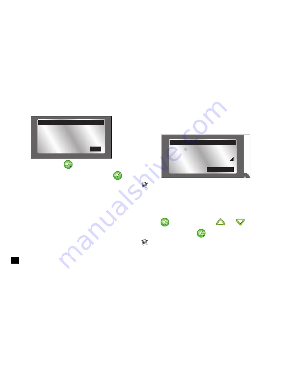
2.  Return to the controller and confirm that the signal 

strength (see above graphic) is good. If signal strength is 

weak, relocate the sensor to a spot closer to the controller.

3.  Press 

 when satisfied.Use the 

 and 

 to adjust 

the calibration setting (default 5: approximately a 1-day 

“watch window”). Press 

.

  The “Cal Setting” number adjusts the time it takes to 

calibrate the sensor. A Cal Setting of ‘0’ calibrates the 

sensor to the 

current

 moisture level in the ground. The 

SOIL 1

DEVICE ID      05952

CORRECT?  

ADD/REMOVE DEVICE

YES

INSTALL SENSOR

IN GROUND

SIGNAL STRENGTH

ADD/REMOVE DEVICE

CONTINUE

Содержание Precision Soil Sensor

Страница 1: ... Built in installation anchor stakes RF reception range 500 152 m LOS line of sight Operating Temperature 14 F 131 F 10 C to 55 C Introduction Congratulations on purchasing Toro s new EVOLUTION controller with the Precision Soil Sensor add on With the Precision Soil Sensor add on you will quickly realize savings in both time and money while keeping your garden healthy and beautiful EVOLUTION Serie...

Страница 2: ...or Menu 7 Navigating the Menu Interface 7 Getting to the Sensors Menu 7 Menu Settings 8 Moisture Now 8 Low Threshold 8 Fine Tuning the Moisture Level 8 Signal Strength 9 Battery Level 9 Calibrate 9 Cal Setting 9 Current Temperature 10 Freeze Off 10 ID 10 Review Screen 11 Appendix A The Low Threshold Setting 11 Appendix B Site Selection and Earth Installation 12 FCC Statement 13 Toro Support 14 Tab...

Страница 3: ...3 The Precision Soil Sensor Add On works with the EVOLUTION Smart Connect receiver It is possible to add up to three soil sensors per controller Overview LED Signal Indicator sold separately ...

Страница 4: ...compartment cover Figure 1 Set cover aside 2 Install the batteries Figure 2 3 Ensure the O ring is in place then install the battery compartment cover When batteries are initially installed the LED signal indicator is red When the receiver links with the sensor the LED changes to green The LED will remain on for 30 minutes to facilitate sensor installation 1 2 3 4 AA AA AA Figure 2 Figure 1 Instal...

Страница 5: ... 4 The EVOLUTION controller waits for the identification signal from the soil sensor If the soil sensor has had batteries installed in the last 30 minutes the controller should detect and add the sensor immediately If the sensor is out in the field it could take up to a half an hour to detect and add the sensor One can remove and reinstall the soil sensor s batteries to achieve immediate sensor de...

Страница 6: ... See Appendix B Site Selection and Earth Installation for complete instructions on good sensor location If soil sensor is not installed in the ground within that 30 minute window the controller removes the sensor and installation will have to be redone 2 Return to the controller and confirm that the signal strength see above graphic is good If signal strength is weak relocate the sensor to a spot ...

Страница 7: ...hed The Soil Sensor Menu The EVOLUTION controller s Soil Sensor menu displays sensor information as well as allows the user to modify certain settings Navigating the Menu Interface Use or to navigate the menu commands To change a value press or to move to the desired field then press and to adjust the value Press to input the desired value Getting to the Sensors Menu 1 Press ADVANCED then 2 Press ...

Страница 8: ...t moisture level as a percentage of the soil 100 is the soil level set after the first calibration see Calibrate the Sensor page 6 LOW THRESHOLD This is the point at which the soil sensor will let the controller resume irrigation of the landscape If you were to compare the soil to a gas tank the low threshold would be the point at which you refill the gas tank For a detailed explanation of the low...

Страница 9: ...the maximum capacity 100 From this fixed reference point the sensor determines when the soil moisture has dropped enough to the Low Threshold to allow watering Manual calibration At some point it might be necessary to recalibrate the sensor in the event of a sensor relocation for example 1 Run an automatic or manual watering operation to thoroughly irrigate the sensor zone 2 Go to the Sensor Menu ...

Страница 10: ...e temperature at which irrigation will be turned off due to cold temperatures 1 or raises or lowers the temperature value 2 Press to input the value It is possible to disable the Freeze Off feature Lowering the temperature past 29 F will show OFF Press the to input the value ID Displays the ID of the selected soil sensor CURRENT TEMP Displays the temperature of the sensor at ground level not at sp...

Страница 11: ... needed The Precision Soil Sensor is preset to restrict watering until the soil moisture level drops to 50 of capacity or 1 2 of the total moisture that can be retained in the soil If you were to draw a comparison to a car s fuel tank 50 of the soil moisture capacity would be similar to using 1 2 of the fuel in the tank before stopping to refill A 50 setting restricts the sprinklers from refilling...

Страница 12: ...receiver communication range 500 line of sight at least 4 feet away from a driveway roof overhang or downspout not in a footpath or recreational area not exposed to overspray from nearby watering zones Earth Installation 1 Move the sensor to the proposed installation site Signal strength is indicated by the LED color as follows Green Excellent Yellow Acceptable Red Not Acceptable Relocate Sensor 2...

Страница 13: ...unications However there is no guarantee that interference will not occur in a particular installation If this equipment generates interference to radio or television reception which can be determined by turning the equipment on and off the user is encouraged to try to correct the interference by one or more of the following measures 1 Reorient or relocate the receiving antenna 2 Increase the sepa...

Страница 14: ...or resulting non use property damage or personal injury resulting from installer s negligence Some states do not allow the exclusion or limitation of incidental or consequential damages so the above limitation or exclusion may not apply to you All implied warranties including those of merchantability and fitness for use are limited to the duration of this express warranty Some states do not allow ...

Страница 15: ...15 Declaration of Uniformity ...

Страница 16: ... 2016 The Toro Company Irrigation Division www toro com 1 877 345 8676 US and Canada evolution toro com international Form Number 373 0807 Rev C Installation Notes ...

Отзывы: