background image

Adjusting the Control Cable

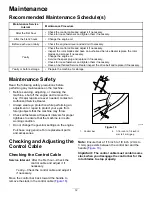
1.

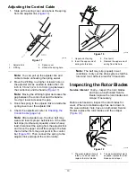
Slide up the spring cover and unhook the spring
from the adjuster link (

Figure 17

).

g006402

Figure 17

1.

Adjuster link

3.

Spring cover

2.

Z-fitting

4.

Unhook the spring here.

Note:

You can pull up the adjuster link and

cable to make unhooking the spring easier.

2.

Move the Z-fitting to a higher or lower hole on
the adjuster link as needed to obtain the 1/16
inch to 1/8 inch (2 mm to 3 mm) gap between
the control bar and the handle (

Figure 17

).

Note:

Moving the Z-fitting higher decreases the

gap between the control bar and the handle;
moving it lower increases the gap.

3.

Hook the spring to the adjuster link and slide the
spring cover over the adjuster link.

4.

Check the adjustment; refer to

Checking the

Control Cable (page 12)

.

Note:

After extended use, the drive belt may

wear and lose its proper belt tension. If the drive
belt slips (continuously squeals) under a heavy
load, disconnect the spring from the adjustor link
and move the upper end of the spring to the hole
that is further from the pivot point in the control
bar (

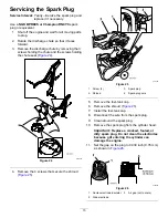
Figure 18

). Then connect the spring to the

adjustor link and adjust the control cable.

g011232

Figure 18

1.

Upper end of spring

3.

Pivot point

2.

Insert the upper end of
spring into this hole

4.

Remove the upper end of
spring from this hole

Note:

The belt may slip (squeal) in wet

conditions; to dry out the drive system, start the
rotor and run it without a load for 30 seconds.

Inspecting the Rotor Blades

Service Interval:

Yearly—Inspect the rotor blades

and have an Authorized Service
Dealer replace the rotor blades and
scraper if necessary.

Before each session, inspect the rotor blades for
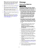
wear. When a rotor-blade edge has worn down to
the wear-indicator hole, have an Authorized Service
Dealer replace the rotor blades and the scraper
(

Figure 19

).

g011544

Figure 19

1.

The wear-indicator hole is
intact; you do not need to
replace the rotor blades.

2.

The wear-indicator hole is
exposed; replace the rotor
blades and scraper.

13


Содержание Power Clear 721 R

Страница 1: ...identified by the safety alert symbol Figure 2 which signals a hazard that may cause serious injury or death if you do not follow the recommended precautions g000502 Figure 2 Safety alert symbol This manual uses 2 words to highlight information Important calls attention to special mechanical information and Note emphasizes general information worthy of special attention Important If you are using ...

Страница 2: ...eration 11 After Operation Safety 11 Preventing Freeze up after Use 11 Maintenance 12 Recommended Maintenance Schedule s 12 Maintenance Safety 12 Checking and Adjusting the Control Cable 12 Inspecting the Rotor Blades 13 Changing the Engine Oil 14 Servicing the Spark Plug 15 Replacing the Drive Belt 16 Storage 17 Storing the Machine 17 Safety This snowthrower is capable of injuring hands and feet ...

Страница 3: ...ment hazard impeller shut off the engine and wait for the auger to stop before leaving the machine 7 Primer 3 Thrown object hazard keep bystanders a safe distance away from the machine 8 Push the primer 3 times to prime the engine 4 Fuel spill hazard do not tip machine backward 9 Read the Operator s Manual before checking the engine oil level 5 Engine switch on decal117 9103 117 9103 Model 38742 o...

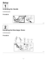
Страница 4: ...Setup 1 Unfolding the Handle No Parts Required Procedure g263299 2 Installing the Discharge Chute No Parts Required Procedure g217715 4 ...

Страница 5: ...3 Filling the Engine with Oil No Parts Required Procedure g253610 4 Adjusting the Control Cable No Parts Required Procedure Refer to Adjusting the Control Cable page 13 5 ...

Страница 6: ... hearing protection Tie back long hair secure loose clothing and do not wear loose jewelry Thoroughly inspect the area where you will use the machine and remove all doormats sleds boards wires and other foreign objects If a shield safety device or decal is damaged illegible or missing repair or replace it before beginning operation Also tighten any loose fasteners Two stage models only Adjust the ...

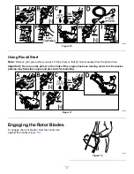
Страница 7: ...rtant For best results purchase only the quantity of fuel that you expect to use in 30 days Otherwise you may use fuel stabilizer conditioner in the machine at all times to keep the fuel fresh longer when used as directed by the fuel stabilizer manufacturer Checking the Engine Oil Level Service Interval Before each use or daily g253610 Figure 9 During Operation During Operation Safety General Safe...

Страница 8: ...ippery surfaces Starting the Engine Using Electric Start Note Remove your glove when you push in the primer so that air cannot escape from the primer hole Important Do not use the primer or the choke if the engine has been running and is hot Excessive priming may flood the engine and prevent it from starting To use the electric starter electric start models only connect a power cord to the electri...

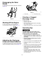
Страница 9: ...from the primer hole Important Do not use the primer or the choke if the engine has been running and is hot Excessive priming may flood the engine and prevent it from starting g258357 Figure 11 Engaging the Rotor Blades To engage the rotor blades hold the control bar against the handle Figure 12 g219303 Figure 12 9 ...

Страница 10: ...lways use a clean out tool never use your hands Operating Tips WARNING The rotor blades can throw stones toys and other foreign objects and cause serious personal injury to you or bystanders Keep the area to be cleared free of all objects that the rotor blades could pick up and throw Keep all children and pets away from the area of operation Remove the snow as soon as possible after it falls Overl...

Страница 11: ...ts from freezing Shut off the engine wait for all moving parts to stop and remove ice and snow from the machine Clean off any snow and ice from the base of the chute Rotate the discharge chute left and right to free it from any ice buildup With the ignition key in the OFF position pull the recoil start handle several times or connect the electrical cord to a power source and the machine and push t...

Страница 12: ... or cleaning the machine shut off the engine and remove the key If major repairs are ever needed contact an Authorized Service Dealer Always wear eye protection while performing an adjustment or repair to protect your eyes from foreign objects that the machine may throw Check all fasteners at frequent intervals for proper tightness to ensure that the machine is in safe working condition Do not cha...

Страница 13: ... a heavy load disconnect the spring from the adjustor link and move the upper end of the spring to the hole that is further from the pivot point in the control bar Figure 18 Then connect the spring to the adjustor link and adjust the control cable g011232 Figure 18 1 Upper end of spring 3 Pivot point 2 Insert the upper end of spring into this hole 4 Remove the upper end of spring from this hole No...

Страница 14: ...plug and tighten it securely 6 Clean around the oil fill cap Figure 21 g006316 Figure 21 1 Oil fill cap 7 Unscrew the oil fill cap and remove it Figure 21 8 With the machine in the operating position carefully pour oil into the oil fill hole to the point of overflow Figure 23 Note You may tip the machine forward handle up to make adding oil easier Remember to return the machine to the operating po...

Страница 15: ...e the 4 screws that secure the shroud Figure 25 g011435 Figure 25 1 Screw 4 3 Spark plug 2 Shroud 4 Spark plug wire 5 Remove the fuel tank cap 6 Remove the shroud Figure 25 7 Install the fuel tank cap 8 Disconnect the wire from the spark plug 9 Clean around the spark plug 10 Remove the spark plug from the cylinder head Important Replace a cracked fouled or dirty spark plug Do not clean the electro...

Страница 16: ...in the chute seal at the front of the discharge chute opening Replacing the Drive Belt If the drive belt becomes worn oil soaked excessively cracked frayed or otherwise damaged replace the belt 1 Remove the drive belt cover by removing the 3 bolts as shown in Figure 28 g008238 Figure 28 1 Drive belt cover 6 Drive belt 2 Bolt 3 7 Rotor shaft 3 Rotor pulley bolt 8 Brake spring unhook from idler arm ...

Страница 17: ...tip the machine either forward or backward with fuel in the fuel tank otherwise fuel may leak out of the machine Do not store the machine with its handle tipped down onto the ground otherwise oil leaks into the engine cylinder and onto the ground and the engine does not start or run 1 On the last refueling of the season add fuel stabilizer to fresh fuel as directed by the fuel stabilizer manufactu...

Страница 18: ...s with paint available from an Authorized Service Dealer Sand affected areas before painting and use a rust preventative to prevent the metal parts from rusting 15 Tighten any loose fasteners Repair or replace any damaged parts 16 Cover the machine and store it in a clean dry place out of the reach of children Allow the engine to cool before storing the machine in any enclosure 18 ...

Страница 19: ...to restaurants grocery stores hotels schools and hospitals and on a wide variety of products Additionally some online and mail order retailers provide Prop 65 warnings on their websites or in catalogs How do the California warnings compare to federal limits Prop 65 standards are often more stringent than federal and international standards There are various substances that require a Prop 65 warnin...

Страница 20: ......

Отзывы: