


8
Installing the Cutting Units
(For Cutting Unit Models 04610
and 04611 Only)
Parts needed for this procedure:
1
Offset Lift Hook
2
Bolts, M10–1.5
1
Gauge bar
1
Bolt (#10 x 5/8 inch)
1
Jam nut (#10)
3
Cutting unit
6
Washer
6
Ball stud
3
Grass Basket
Procedure
Note:
When sharpening, setting the height-of-cut
or performing other maintenance procedures on the
cutting units, store the cutting unit reel motors in the
support tubes to prevent damage to the hoses.
Important:
Do not raise the suspension to the
transport position when the reel motors are in the
holders in the machine frame. Damage to the
motors or hoses could result
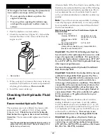
Important:
Whenever the cutting unit has to be
tipped to expose bedknife/reel, prop up rear of
cutting unit to make sure nuts on back end of
bedbar adjusting screws are not resting on work
surface (Figure 11).
Figure 11
1.
Prop (not provided)
2.
Bedknife adjusting screw
nut (2)
1. Remove the cutting units from the cartons. Assemble
and adjust them as listed in the cutting unit
Operator’s
Manual.
Use the gauge bar from the loose parts kit
to adjust the height of cut.
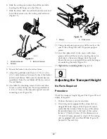
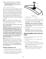
2. Install the offset lift hook (Figure 12) to the top of
the cutting unit with (2) M10–1.5 bolts. Torque the
bolts to 25–30 ft–lbs. (34–40 N
⋅
m). The offset lift
hook should be positioned with hook forward.
Figure 12
1.
Offset lift hook
3. All cutting units are shipped with the counter weight
mounted to the left end and the motor mount and
drive coupler mounted to the right end of the cutting
unit. To mount the cutting unit in the right front
position, proceed as follows:
18
Содержание Greensmaster 3250-D
Страница 49: ...Schematics Electrical Schematic Rev B 49 ...
Страница 50: ...Hydraulic Schematic Rev C 50 ...
Страница 51: ...Notes 51 ...