background image

Safety Instructions

DANGER

This safety symbol means danger. When you see this symbol,
carefully read the instructions that follow. Failure to obey the
instructions could cause serious permanent injury, disability, or
death.

WARNING

This safety symbol means warning. When you see this symbol,
carefully read the instructions that follow. Failure to obey the
instructions can result in serious injury.

CAUTION

This safety symbol means caution. When you see this symbol,
carefully read the instructions that follow. Failure to obey the
instructions can result in minor to moderate injury and/or damage
to property or equipment.

Think Safety First

Avoid unexpected starting of engine…

Always turn off the engine, remove the ignition key and disconnect the spark plug
wire(s) before cleaning, adjusting, or repair.

Avoid lacerations and amputations…

Stay clear of all moving parts whenever the engine is running. Treat all normally
moving parts as if they were moving whenever the engine is running or has
the potential to start.

Avoid burns…

Do not touch the engine, muffler, or other components, which may be hot during
operation, while the unit is running or shortly after it has been running.

Avoid fires and explosions…

Use extreme care in handling fuel. It is flammable and its vapors are explosive.
Extinguish all cigarettes, cigars, pipes, and other sources of ignition. Avoid
spilling fuel and never smoke while working with any type of fuel or lubricant.
Wipe up any spilled fuel or oil immediately. Never remove the fuel cap or add
fuel when the engine is running. Always use approved, labeled containers for
storing or transporting fuel and lubricants. Do not add or drain fuel in an enclosed
space. Do not store the machine or fuel container where there is an open flame,
spark, or pilot light, such as on a water heater or other appliance.

Avoid asphyxiation…

Do not operate an engine in a confined area without proper ventilation.

Avoid injury from batteries…

Safety: Safety Instructions

Page 1–2

60V MAX e21 Power Clear® Snow Thrower with

Flex—Force Power System® Service Manual

3438-775 Rev A


Содержание Flex-Force Power System 39901

Страница 1: ...e21 Power Clear Snow Thrower with Flex Force Power System Service Manual Published May 2020 2020 The Toro Company 8111 Lyndale Avenue South Bloomington MN 55420 Original Instructions EN Contact us at www Toro com All Rights Reserved ...

Страница 2: ...Revision History Revision History Page 2 60V MAX e21 Power Clear Snow Thrower with Flex Force Power System Service Manual 3438 775 Rev A ...

Страница 3: ... this manual We are hopeful that you will find this manual a valuable addition to your service shop If you have any questions or comments regarding this manual please contact us at the following address The Toro Company RLC SWS Customer Care Department 8111 Lyndale Avenue South Bloomington MN 55420 The Toro Company reserves the right to change product specifications or make changes to this manual ...

Страница 4: ...mponent orientation that may not be obvious Critical Torque This icon is used to highlight an assembly torque requirement that is different than what is recommended in the Standard Torque Tables Fluid Specifications This icon is used to highlight fluid specifications and capacities that are less common and may not appear on the machine service decal or in the machine Operator s Manual Note Refer t...

Страница 5: ...1 General Information 4 2 Service and Repairs 4 3 Chapter 5 Drive System 5 1 General Information 5 2 Service and Repairs 5 3 Chapter 6 Chute 6 1 General Information 6 2 Service and Repairs 6 3 Chapter 7 Controls 7 1 General Information 7 2 Service and Repairs 7 3 Chapter 8 Motor 8 1 General Information 8 2 Service and Repairs 8 3 60V MAX e21 Power Clear Snow Thrower with Flex Force Power System Se...

Страница 6: ...Preface Page 6 60V MAX e21 Power Clear Snow Thrower with Flex Force Power System Service Manual 3438 775 Rev A ...

Страница 7: ...Chapter 1 Safety Table of Contents Safety Instructions 1 2 Think Safety First 1 2 60V MAX e21 Power Clear Snow Thrower with Flex Force Power System Service Manual Page 1 1 Safety 3438 775 Rev A ...

Страница 8: ...hey were moving whenever the engine is running or has the potential to start Avoid burns Do not touch the engine muffler or other components which may be hot during operation while the unit is running or shortly after it has been running Avoid fires and explosions Use extreme care in handling fuel It is flammable and its vapors are explosive Extinguish all cigarettes cigars pipes and other sources...

Страница 9: ...nozzles that eject hydraulic fluid under high pressure Do not use your hands to search for leaks Hydraulic fluid escaping under pressure can have sufficient force to penetrate under the skin and cause serious injury Seek medical attention right away if hydraulic fluid gets in the skin Personal Protective Equipment Tie back long hair and do not wear loose clothing or jewelry Use appropriate persona...

Страница 10: ...quare feet of fire it can extinguish Geometric symbol red square Class C fires involve electrical equipment such as appliances wiring circuit breakers and outlets Never use water to extinguish class C fires the risk of electrical shock is far too great Class C extinguishers do not have a numerical rating The C classification means the extinguishing agent is non conductive Geometric symbol blue cir...

Страница 11: ...Contents Specifications 2 2 Torque Specifications 2 3 Equivalents and Conversions 2 8 U S to Metric Conversions 2 9 60V MAX e21 Power Clear Snow Thrower with Flex Force Power System Service Manual Page 2 1 Specifications and Maintenance 3438 775 Rev A ...

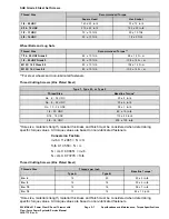
Страница 12: ...row Distance Up to 12 m 40 ft Clearing Width 53 cm 21 inches Weight 27 2 kg 60 lb Length 145 cm 57 inches Width 53 cm 21 inches Height 72 cm 28 5 inches Specifications and Maintenance Specifications Page 2 2 60V MAX e21 Power Clear Snow Thrower with Flex Force Power System Service Manual 3438 775 Rev A ...

Страница 13: ...similar condition which affects the installation As noted in the following tables torque values should be reduced by 25 for lubricated fasteners to achieve the similar stress as a dry fastener Torque values may also have to be reduced when the fastener is threaded into aluminum or brass The specific torque value should be determined based on the aluminum or brass material strength fastener size le...

Страница 14: ...s and Screws g272209 Figure 2 1 Class 8 8 2 Class 10 9 Specifications and Maintenance Torque Specifications Page 2 4 60V MAX e21 Power Clear Snow Thrower with Flex Force Power System Service Manual 3438 775 Rev A ...

Страница 15: ...F 29 3 29 3 39 4 55 6 75 8 77 8 104 11 1 2 13 UNC 30 3 48 7 65 9 75 8 102 11 105 11 142 15 1 2 20 UNF 32 4 53 7 72 9 85 9 115 12 120 12 163 16 5 8 11 UNC 65 10 88 12 119 16 150 15 203 20 210 21 285 28 5 8 18 UNF 75 10 95 15 129 20 170 18 230 24 240 24 325 33 3 4 10 UNC 93 12 140 20 190 27 265 27 359 37 375 38 508 52 3 4 16 UNF 115 15 165 25 224 34 300 30 407 41 420 43 569 58 7 8 9 UNC 140 20 225 2...

Страница 16: ...he table above by 25 for lubricated fasteners Lubricated fasteners are defined as threads coated with a lubricant such as oil graphite or thread sealant such as Loctite Torque values may have to be reduced when installing fasteners into threaded aluminum or brass The specific torque value should be determined based on the fastener size the aluminum or base material strength length of thread engage...

Страница 17: ...4 20 UNC 85 15 in lb 5 16 18 UNC 110 20 in lb 3 8 16 UNC 200 100 in lb Hole size material strength material thickness and finish must be considered when determining specific torque values All torque values are based on non lubricated fasteners Conversion Factors in lb X 11 2985 N cm ft lb X 1 3558 N m N cm X 0 08851 in lb N cm X 0 73776 ft lb Thread Cutting Screws Zinc Plated Steel Threads per Inc...

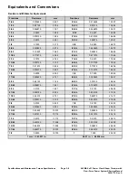
Страница 18: ... 2500 6 350 3 4 0 7500 19 050 17 64 0 265625 6 747 49 64 0 765625 19 447 9 32 0 28125 7 144 25 32 0 78125 19 844 19 64 0 296875 7 541 51 64 0 796875 20 241 5 16 0 3125 7 541 13 16 0 8125 20 638 21 64 0 328125 8 334 53 64 0 828125 21 034 11 32 0 34375 8 731 27 32 0 84375 21 431 23 64 0 359375 9 128 55 64 0 859375 21 828 3 8 0 3750 9 525 7 8 0 8750 22 225 25 64 0 390625 9 922 57 64 0 890625 22 622 1...

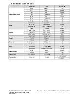
Страница 19: ... 02832 Volume Cubic Inches Cubic Centimeters 16 39 Tons Short Metric Tons 0 9078 Pounds Kilograms 0 4536 Weight Ounces Grams 28 3495 Pressure Pounds Square Inch Kilopascal 6 895 Foot Pounds Newton Meters 1 356 Foot Pounds Kilogram Meters 0 1383 Work Inch Pounds Kilogram Centimeters 1 152144 Quarts Liters 0 9463 Liquid Volume Gallons Liters 3 785 Liquid Flows Gallons Minute Liters Minute 3 785 1 Su...

Страница 20: ...Specifications and Maintenance Torque Specifications Page 2 10 60V MAX e21 Power Clear Snow Thrower with Flex Force Power System Service Manual 3438 775 Rev A ...

Страница 21: ...Chapter 3 Troubleshooting Table of Contents General Troubleshooting 3 4 60V MAX e21 Power Clear Snow Thrower with Flex Force Power System Service Manual Page 3 1 Troubleshooting 3438 775 Rev A ...

Страница 22: ... the problem Assess Performance Ensure you have all the necessary tools for testing Test all potential causes of the failure A Reevaluate and create new hypotheses if necessary Repair R Return the unit to service by repairing rebuilding or replacing Solution Confirmation Did the issue go away Was the root cause of the issue correctly repaired S Are there any other new symptoms Troubleshooting Gene...

Страница 23: ...cessary Internal Error Code 10 1 Verify motor driver functionality 2 Replace motor driver as necessary Communication High Error from Battery Communication 11 1 Verify motor driver functionality 2 Replace motor driver as necessary Motor Error 12 1 Verify motor driver functionality 2 Replace motor driver as necessary Current Error 13 1 Cutting motor overloaded Reduce load 2 Verify cutting chamber is...

Страница 24: ...oubleshooting See Operator s Manual for troubleshooting information Troubleshooting General Troubleshooting Page 3 4 60V MAX e21 Power Clear Snow Thrower with Flex Force Power System Service Manual 3438 775 Rev A ...

Страница 25: ... Table of Contents General Information 4 2 Service and Repairs 4 3 Battery Track Assembly Replacement 4 4 60V MAX e21 Power Clear Snow Thrower with Flex Force Power System Service Manual Page 4 1 Battery 3438 775 Rev A ...

Страница 26: ...General Information This is a 60 volt MAX snowthrower Battery General Information Page 4 2 60V MAX e21 Power Clear Snow Thrower with Flex Force Power System Service Manual 3438 775 Rev A ...

Страница 27: ...mbly g320492 Figure 3 1 Battery Container Skirt 3 60v Charger 2 Battery Track Assembly 4 Battery Container 60V MAX e21 Power Clear Snow Thrower with Flex Force Power System Service Manual Page 4 3 Battery Service and Repairs 3438 775 Rev A ...

Страница 28: ...emove the chute control rod from the machine 4 Remove the 2 screws securing the controller cover to the battery container skirt Remove the controller cover from the machine 5 Remove the 4 screws securing the motor driver to the battery container skirt g320303 Figure 4 6 Lift the motor driver from the battery container skirt and disconnect all the wire attachments Remove the motor driver from the b...

Страница 29: ...move the battery container skirt from the machine g320289 Figure 6 9 Flip the machine over so the auger housing is facing the floor Remove the 2 screws securing the battery track assembly to the battery container 60V MAX e21 Power Clear Snow Thrower with Flex Force Power System Service Manual Page 4 5 Battery Service and Repairs 3438 775 Rev A ...

Страница 30: ...k assembly from the battery container skirt g320308 Figure 8 Battery Track Assembly Installation 1 Install the battery track assembly into the battery container Install the 2 screws securing the battery track assembly to the battery container Torque the screws to 1 1 1 7 N m 10 15 in lb Battery Service and Repairs Page 4 6 60V MAX e21 Power Clear Snow Thrower with Flex Force Power System Service M...

Страница 31: ...1 1 1 7 N m 10 15 in lb g320309 Figure 10 3 Flip the machine over so the wheels are on the ground Install the battery container skirt onto the battery container Install the 3 screws securing the battery container skirt to the battery container Torque the screws to 1 1 1 7 N m 10 15 in lb 60V MAX e21 Power Clear Snow Thrower with Flex Force Power System Service Manual Page 4 7 Battery Service and R...

Страница 32: ...crews to 1 1 1 7 N m 10 15 in lb g320276 Figure 12 5 Connect all the wire attachments to the motor driver 6 Install the 4 screws securing the motor driver to the battery container skirt Torque the screws to 1 1 1 7 N m 10 15 in lb Battery Service and Repairs Page 4 8 60V MAX e21 Power Clear Snow Thrower with Flex Force Power System Service Manual 3438 775 Rev A ...

Страница 33: ...ntrol rod into the machine WARNING When removing or installing the battery do not allow the battery terminals to touch any metal parts of the machine Do not allow metal tools to short between the battery terminals and metal parts of the machine 9 Install the battery into the machine 60V MAX e21 Power Clear Snow Thrower with Flex Force Power System Service Manual Page 4 9 Battery Service and Repair...

Страница 34: ...Battery Service and Repairs Page 4 10 60V MAX e21 Power Clear Snow Thrower with Flex Force Power System Service Manual 3438 775 Rev A ...

Страница 35: ... of Contents General Information 5 2 Service and Repairs 5 3 Ribbed V Belt Replacement 5 4 Rotor Replacement 5 6 60V MAX e21 Power Clear Snow Thrower with Flex Force Power System Service Manual Page 5 1 Drive System 3438 775 Rev A ...

Страница 36: ...l Information This is a free wheeling snowthrower with no drive assist Drive System General Information Page 5 2 60V MAX e21 Power Clear Snow Thrower with Flex Force Power System Service Manual 3438 775 Rev A ...

Страница 37: ... Sideplate Cap 5 LH Extension 2 Ball Bearing 6 Ribbed Belt 3 RH Extension 7 Rotor Pulley Asm 4 Rotor 8 Belleville Washer 60V MAX e21 Power Clear Snow Thrower with Flex Force Power System Service Manual Page 5 3 Drive System Service and Repairs 3438 775 Rev A ...

Страница 38: ...ne 2 Lift the battery cover and remove the battery from the machine 3 Remove the plastic screw securing the belt cover to the LH frame plate assembly Remove the 3 screws securing the belt cover to the housing Remove the belt cover from the machine g320499 Figure 15 1 Plastic Screw 2 Screws 4 Remove the screw and Belleville washer securing the rotor pulley assembly to the rotor shaft g323087 Figure...

Страница 39: ... threads of motor pulley 3 Thread the new ribbed V belt around the motor pulley and route the ribbed V belt around the rotor pulley assembly Note Install new ribbed V belt each time the V belt is installed Failure to do so can result in impaired rotor function 4 Install the belt cover to the housing Install the plastic screw securing the belt cover to the LH frame plate assembly Install the 3 scre...

Страница 40: ...ce and wait for all moving parts to stop WARNING When removing or installing the battery do not allow the battery terminals to touch any metal parts of the machine Do not allow metal tools to short between the battery terminals and metal parts of the machine 2 Lift the battery cover and remove the battery from the machine 3 Remove the ribbed V belt Ribbed V Belt Replacement page 5 4 4 Remove the 3...

Страница 41: ...he LH frame plate to the housing g320272 Figure 20 6 Remove the 3 screws securing the RH frame plate to the housing and the RH extension 60V MAX e21 Power Clear Snow Thrower with Flex Force Power System Service Manual Page 5 7 Drive System Service and Repairs 3438 775 Rev A ...

Страница 42: ... securing the RH frame plate to the housing g320294 Figure 22 8 Remove the 2 screws securing the RH frame plate to the housing Drive System Service and Repairs Page 5 8 60V MAX e21 Power Clear Snow Thrower with Flex Force Power System Service Manual 3438 775 Rev A ...

Страница 43: ...otor Installation 1 Slide and install the rotor assembly to the housing 2 Install the 2 screws securing the RH frame plate to the housing Torque the screws to 2 8 4 N m 25 35 in lb 60V MAX e21 Power Clear Snow Thrower with Flex Force Power System Service Manual Page 5 9 Drive System Service and Repairs 3438 775 Rev A ...

Страница 44: ... the 3 screws securing the RH frame plate to the housing Torque the screws to 2 3 2 8 N m 20 25 in lb g320294 Figure 26 Drive System Service and Repairs Page 5 10 60V MAX e21 Power Clear Snow Thrower with Flex Force Power System Service Manual 3438 775 Rev A ...

Страница 45: ...the 2 screw securing the LH frame plate to the housing Torque the screws to 2 8 4 N m 25 35 in lb g320272 Figure 28 6 Install the 3 screws securing the LH frame plate to the housing and the LH extension Torque the screws to 5 6 8 N m 45 60 in lb 60V MAX e21 Power Clear Snow Thrower with Flex Force Power System Service Manual Page 5 11 Drive System Service and Repairs 3438 775 Rev A ...

Страница 46: ...attery do not allow the battery terminals to touch any metal parts of the machine Do not allow metal tools to short between the battery terminals and metal parts of the machine 8 Install the battery into the machine Drive System Service and Repairs Page 5 12 60V MAX e21 Power Clear Snow Thrower with Flex Force Power System Service Manual 3438 775 Rev A ...

Страница 47: ...e of Contents General Information 6 2 Service and Repairs 6 3 Chute Gear Replacement 6 4 Chute Replacement 6 14 60V MAX e21 Power Clear Snow Thrower with Flex Force Power System Service Manual Page 6 1 Chute 3438 775 Rev A ...

Страница 48: ...n This snowthrower is equipped with a manual rotation chute and throw distance selection Chute General Information Page 6 2 60V MAX e21 Power Clear Snow Thrower with Flex Force Power System Service Manual 3438 775 Rev A ...

Страница 49: ...ery Cover 6 Chute Gear 2 Chute 7 Rear Chute 3 Shroud 8 Sector Gear 4 Controller Cover 9 Plastic Screw 5 Gear Bracket 10 Belt Cover 60V MAX e21 Power Clear Snow Thrower with Flex Force Power System Service Manual Page 6 3 Chute Service and Repairs 3438 775 Rev A ...

Страница 50: ...emove the chute control rod from the machine 4 Remove the 2 screws securing the controller cover to the battery container skirt Remove the controller cover from the battery container 5 Remove the 4 screws securing the motor driver to the battery container skirt g320303 Figure 31 6 Lift the motor driver from the battery container skirt and disconnect all the wire attachments Remove the motor driver...

Страница 51: ... container Remove the battery container skirt g320289 Figure 33 9 Remove the 4 screws and washers securing the battery container to the bulkhead Remove the battery container from the bulkhead 60V MAX e21 Power Clear Snow Thrower with Flex Force Power System Service Manual Page 6 5 Chute Service and Repairs 3438 775 Rev A ...

Страница 52: ...oud from the rear chute 11 Remove the 2 screws securing the LH frame assembly plate to the bulkhead g320271 Figure 35 12 Remove the 2 screws securing the RH frame assembly plate to the bulkhead Chute Service and Repairs Page 6 6 60V MAX e21 Power Clear Snow Thrower with Flex Force Power System Service Manual 3438 775 Rev A ...

Страница 53: ...bulkhead to the upper housing g320494 Figure 37 1 Screw 2 Washer 14 Remove the 2 screws securing the lower bulkhead to the lower housing Remove the bulkhead from the housing 60V MAX e21 Power Clear Snow Thrower with Flex Force Power System Service Manual Page 6 7 Chute Service and Repairs 3438 775 Rev A ...

Страница 54: ...et and attached sector gear from the chute gear 17 Remove the chute gear from the rear chute Chute Gear Installation 1 Install the chute gear on the rear chute so that the chute gear arrow is aligned between the two vertical lines on the chute Chute Service and Repairs Page 6 8 60V MAX e21 Power Clear Snow Thrower with Flex Force Power System Service Manual 3438 775 Rev A ...

Страница 55: ...he sector gear between the two does of the chute gear g321112 Figure 41 3 Install the 2 screws securing the gear bracket to the rear chute and housing Torque the screws to 1 1 1 7 N m 10 15 in lb 60V MAX e21 Power Clear Snow Thrower with Flex Force Power System Service Manual Page 6 9 Chute Service and Repairs 3438 775 Rev A ...

Страница 56: ...ing Torque the screws to 2 26 2 82 N m 20 25 in lb g320494 Figure 43 1 Screw 2 Washer 5 Install the 2 screws securing the lower bulkhead to the lower housing Torque the screws to 2 26 2 82 N m 20 25 in lb Chute Service and Repairs Page 6 10 60V MAX e21 Power Clear Snow Thrower with Flex Force Power System Service Manual 3438 775 Rev A ...

Страница 57: ...head Torque the screws to 2 26 2 82 N m 20 25 in lb g320273 Figure 45 7 Install the 2 screws securing the LH frame plate assembly to the bulkhead Torque the screws to 2 26 2 82 N m 20 25 in lb 60V MAX e21 Power Clear Snow Thrower with Flex Force Power System Service Manual Page 6 11 Chute Service and Repairs 3438 775 Rev A ...

Страница 58: ...the screws to 1 1 1 7 N m 10 15 in lb 9 Install the battery container to the bulk head Install the 4 screws and washers securing the battery container to the bulkhead Torque the screws to 1 1 1 7 N m 10 15 in lb g320297 Figure 47 Chute Service and Repairs Page 6 12 60V MAX e21 Power Clear Snow Thrower with Flex Force Power System Service Manual 3438 775 Rev A ...

Страница 59: ... the battery container skirt to the battery container Torque the screws to 1 1 1 7 N m 10 15 in lb g320289 Figure 49 12 Connect all wiring to the motor driver 13 Install the 4 screws securing the motor driver to the battery container skirt Torque the screws to 1 1 1 7 N m 10 15 in lb 60V MAX e21 Power Clear Snow Thrower with Flex Force Power System Service Manual Page 6 13 Chute Service and Repair...

Страница 60: ...ry into the machine Chute Replacement Chute Removal 1 Park the machine on a level surface and wait for all moving parts to stop WARNING When removing or installing the battery do not allow the battery terminals to touch any metal parts of the machine Do not allow metal tools to short between the battery terminals and metal parts of the machine 2 Lift the battery cover and remove the battery from t...

Страница 61: ...re 52 Chute Installation 1 Install the chute and rear chute onto the housing 2 Install the 4 screws securing the rear chute to the housing Torque the screws to 1 7 2 3 N m 15 20 in lb 60V MAX e21 Power Clear Snow Thrower with Flex Force Power System Service Manual Page 6 15 Chute Service and Repairs 3438 775 Rev A ...

Страница 62: ...attery do not allow the battery terminals to touch any metal parts of the machine Do not allow metal tools to short between the battery terminals and metal parts of the machine 4 Install the battery into the machine Chute Service and Repairs Page 6 16 60V MAX e21 Power Clear Snow Thrower with Flex Force Power System Service Manual 3438 775 Rev A ...

Страница 63: ...ls Table of Contents General Information 7 2 Service and Repairs 7 3 Dash Panel Assembly Replacement 7 4 60V MAX e21 Power Clear Snow Thrower with Flex Force Power System Service Manual Page 7 1 Controls 3438 775 Rev A ...

Страница 64: ...thrower is equipped with a push button motor start and safety switch located in the handle lever Controls General Information Page 7 2 60V MAX e21 Power Clear Snow Thrower with Flex Force Power System Service Manual 3438 775 Rev A ...

Страница 65: ...sembly g320410 Figure 54 1 Handle Screw 4 Flange Nut 2 Bail Key 5 Chute Control Rod 3 Dash Panel Asm 60V MAX e21 Power Clear Snow Thrower with Flex Force Power System Service Manual Page 7 3 Controls Service and Repairs 3438 775 Rev A ...

Страница 66: ...ort between the battery terminals and metal parts of the machine 2 Lift the battery cover and remove the battery from the machine 3 Remove the 2 screws securing the controller cover to the battery container skirt 4 Remove the 4 screws securing the motor driver to the battery container skirt g320303 Figure 55 5 Disconnect the harness from the motor driver Controls Service and Repairs Page 7 4 60V M...

Страница 67: ...0304 Figure 56 6 Remove the screw securing battery container skirt to the battery container g320521 Figure 57 60V MAX e21 Power Clear Snow Thrower with Flex Force Power System Service Manual Page 7 5 Controls Service and Repairs 3438 775 Rev A ...

Страница 68: ...5 screws securing the front and rear dash panels g320298 Figure 59 9 Remove the 4 flange nuts and 4 handle screws securing the front and rear dash panels onto the upper handle assembly Controls Service and Repairs Page 7 6 60V MAX e21 Power Clear Snow Thrower with Flex Force Power System Service Manual 3438 775 Rev A ...

Страница 69: ...andle assembly 2 Install the 4 nuts and 4 handle screws securing the front and rear dash panels onto the upper handle Torque the flange nuts to 4 5 5 6 N m 40 50 in lb g320295 Figure 61 3 Install 5 screws securing the front and rear dash panels Torque the screws to 1 1 1 7 N m 10 15 in lb 60V MAX e21 Power Clear Snow Thrower with Flex Force Power System Service Manual Page 7 7 Controls Service and...

Страница 70: ...e battery container 5 Install the screw securing battery container skirt to the battery container Torque the screw to 1 1 1 7 N m 10 15 in lb g320521 Figure 63 Controls Service and Repairs Page 7 8 60V MAX e21 Power Clear Snow Thrower with Flex Force Power System Service Manual 3438 775 Rev A ...

Страница 71: ...o the battery container skirt Torque the screws to 1 1 1 7 N m 10 15 in lb g320303 Figure 65 8 Install the 2 screws securing the controller cover to the battery container skirt Torque the screws to 1 1 1 7 N m 10 15 in lb 60V MAX e21 Power Clear Snow Thrower with Flex Force Power System Service Manual Page 7 9 Controls Service and Repairs 3438 775 Rev A ...

Страница 72: ...terminals to touch any metal parts of the machine Do not allow metal tools to short between the battery terminals and metal parts of the machine 9 Install the battery into the machine Controls Service and Repairs Page 7 10 60V MAX e21 Power Clear Snow Thrower with Flex Force Power System Service Manual 3438 775 Rev A ...

Страница 73: ... of Contents General Information 8 2 Service and Repairs 8 3 Motor Driver Replacement 8 4 Motor Replacement 8 5 60V MAX e21 Power Clear Snow Thrower with Flex Force Power System Service Manual Page 8 1 Motor 3438 775 Rev A ...

Страница 74: ...nowthrower comes with a pulley installed and a 60 volt motor The 60 volt motor is not serviceable Motor General Information Page 8 2 60V MAX e21 Power Clear Snow Thrower with Flex Force Power System Service Manual 3438 775 Rev A ...

Страница 75: ...and Motor Driver Assembly g320493 Figure 66 1 Motor Driver 3 Motor Pulley 2 60v Snowblower Motor 60V MAX e21 Power Clear Snow Thrower with Flex Force Power System Service Manual Page 8 3 Motor Service and Repairs 3438 775 Rev A ...

Страница 76: ...rod from the machine 4 Remove the 2 screws securing the controller cover to the battery 5 Remove the 4 screws securing the motor driver to the battery container skirt g320303 Figure 67 6 Lift the motor driver from the battery container skirt and disconnect all the wire attachments Remove the motor driver Motor Driver Installation 1 Connect all the wire attachments to the motor driver 2 Install the...

Страница 77: ...he machine Motor Replacement Motor Removal 1 Park the machine on a level surface and wait for all moving parts to stop WARNING When removing or installing the battery do not allow the battery terminals to touch any metal parts of the machine Do not allow metal tools to short between the battery terminals and metal parts of the machine 2 Lift the battery cover and remove the battery from the machin...

Страница 78: ...battery container skirt to the battery container Remove the battery container skirt g320289 Figure 70 7 Remove the 4 screws and 4 washers securing the battery container to the bulk head Remove the battery container from the machine Motor Service and Repairs Page 8 6 60V MAX e21 Power Clear Snow Thrower with Flex Force Power System Service Manual 3438 775 Rev A ...

Страница 79: ...ud from the machine 9 Remove the 2 screws securing the LH frame assembly plate to the bulkhead g320271 Figure 72 10 Remove the 2 screws securing the RH frame assembly plate to the bulkhead 60V MAX e21 Power Clear Snow Thrower with Flex Force Power System Service Manual Page 8 7 Motor Service and Repairs 3438 775 Rev A ...

Страница 80: ...lkhead to the upper housing g320494 Figure 74 1 Screw 2 Washer 12 Remove the 2 screws securing the lower bulkhead to the lower housing Remove the bulkhead from the housing Motor Service and Repairs Page 8 8 60V MAX e21 Power Clear Snow Thrower with Flex Force Power System Service Manual 3438 775 Rev A ...

Страница 81: ...securing the belt cover to the housing Remove the belt cover from the machine g320499 Figure 76 1 Plastic Screw 2 Screws 14 Remove the screw and Belleville washer securing the rotor pulley assembly to the rotor shaft 60V MAX e21 Power Clear Snow Thrower with Flex Force Power System Service Manual Page 8 9 Motor Service and Repairs 3438 775 Rev A ...

Страница 82: ...78 16 Remove the ribbed V belt from the rotor pulley assembly and the motor pulley 17 Remove the 3 screws securing the motor to the LH frame plate Remove the motor from LH frame plate Motor Service and Repairs Page 8 10 60V MAX e21 Power Clear Snow Thrower with Flex Force Power System Service Manual 3438 775 Rev A ...

Страница 83: ...ure 79 g320311 Figure 80 Motor Installation 1 Route motor pulley through LH frame plate pass through hole 60V MAX e21 Power Clear Snow Thrower with Flex Force Power System Service Manual Page 8 11 Motor Service and Repairs 3438 775 Rev A ...

Страница 84: ...reads 5 Thread the new ribbed V belt around the motor pulley and route the ribbed V belt around the rotor pulley assembly Note Install a new ribbed V belt each time the ribbed V belt is installed Failure to do so can result in impaired rotor function 6 Install the belt cover to the housing Install the plastic screw securing the belt cover to the LH frame plate assembly Install the 3 screws securin...

Страница 85: ...er bulkhead to the upper housing Torque the screws to 2 26 2 82 N m 20 25 in lb g320494 Figure 84 1 Screw 2 Washer 8 Install the 2 screws securing the lower bulkhead to the lower housing Torque the screws to 2 26 2 82 N m 20 25 in lb 60V MAX e21 Power Clear Snow Thrower with Flex Force Power System Service Manual Page 8 13 Motor Service and Repairs 3438 775 Rev A ...

Страница 86: ...d Torque the screws to 2 26 2 82 N m 20 25 in lb g320273 Figure 86 10 Install the 2 screws securing the LH frame assembly plate to the bulkhead Torque the screws to 2 26 2 82 N m 20 25 in lb Motor Service and Repairs Page 8 14 60V MAX e21 Power Clear Snow Thrower with Flex Force Power System Service Manual 3438 775 Rev A ...

Страница 87: ...screws and 4 washers securing the battery container to the bulk head Torque the screws to 2 26 2 82 N m 20 25 in lb g320297 Figure 88 13 Install the battery container skirt to the battery container Install the 3 screws securing the battery container skirt to the battery container Torque the screws to 1 1 1 7 N m 10 15 in lb 60V MAX e21 Power Clear Snow Thrower with Flex Force Power System Service ...

Страница 88: ... 8 4 16 Install the chute control rod WARNING When removing or installing the battery do not allow the battery terminals to touch any metal parts of the machine Do not allow metal tools to short between the battery terminals and metal parts of the machine 17 Install the battery into the machine Motor Service and Repairs Page 8 16 60V MAX e21 Power Clear Snow Thrower with Flex Force Power System Se...

Отзывы: