background image

4.

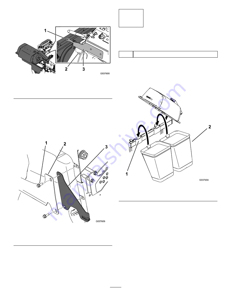
Secure the bagger frame to the front mount
bracket using a carriage bolt (3/8 x 1 inch) and
nut (3/8 inch) as shown in

Figure 16

.

g037650

Figure 16

1.

Nut (3/8 inch)

3.

Front mount bracket

2.

Carriage bolt (3/8 x 1 inch)

5.

Tighten the bagger frame and front mount
bracket nuts.

6.

Install the fuel tank; refer to the

Operator’s

Manual

for the machine.

Note:

When you install the fuel tank bracket,

install the rear mount bracket between the
control tower and the fuel-tank bracket.

g037609

Figure 17

1.

Bolt

3.

Rear mount bracket

2.

Fuel tank bracket

7.

Raise the cushion.

6

Installing the Bags

Parts needed for this procedure:

2

Bag

Procedure

1.

Unlatch and open the hood assembly.

2.

Install the bags onto bag mounts (

Figure 18

).

g037656

Figure 18

1.

Bag mount

2.

Bag

3.

Close and latch the hood assembly.

12


Содержание E-Z Vac 78570

Страница 1: ...ction properly Contact your Authorized Service Dealer to obtain the corresponding necessary parts For more information visit us at www Toro com E Z Vac Twin Bagger 2016 and After Grandstand Mower Model No 78570 Serial No 400000000 and Up Register at www Toro com Original Instructions EN 3415 397 C ...

Страница 2: ...ers on the product Write the numbers in the space provided g037659 Figure 1 1 Blower model and serial number location Model No Serial No g037658 Figure 2 1 Bagger model and serial number location Model No Serial No This manual identifies potential hazards and has safety messages identified by the safety alert symbol Figure 3 which signals a hazard that may cause serious injury or death if you do n...

Страница 3: ...struction from the bagging system Never do maintenance or repairs while the engine is running WARNING When the bagger is in operation the blower is rotating and can cut off or injure hands and fingers Before adjusting cleaning repairing and inspecting the blower and before unclogging the chute shut off the engine and wait for all moving parts to stop Remove the key Use a stick or similar object no...

Страница 4: ...when operating the machine in reverse Use care when loading or unloading the machine into a trailer or truck Never operate with the discharge deflector raised removed or altered unless you are using a grass catcher Keep your hands and feet away from moving parts Do not make adjustments with the engine running Stop the machine on level ground disengage the drives set the parking brake and shut off ...

Страница 5: ...ights installed decal136 4087 136 4087 1 Warning read the Operator s Manual 4 Cutting dismemberment hazard impeller keep away from moving parts keep all guards and covers in place 2 Warning wear hearing protection 5 Cutting dismemberment hazard impeller disengage the PTO remove the ignition key and wait for all moving parts to stop 3 Thrown object hazard do not run the blower without the entire co...

Страница 6: ...ont mount bracket 1 Lower mount bracket 1 Rear mount bracket 1 Right mount bracket 1 Flat washer 2 Bolt 3 8 x 4 inches 2 Carriage bolt 3 8 x 1 inch 1 Nut 3 8 inch 1 Carriage bolt 1 4 x 5 8 inch 2 4 Nut 1 4 inch 2 Install the brackets Bagger frame assembly 1 Clevis pin 2 Hairpin cotter 3 Thrust washer 1 Nut 3 8 inch 1 5 Carriage bolt 3 8 x 1 inch 1 Install the bagger frame 6 Bag 2 Install the bags ...

Страница 7: ...o ease installation 2 Installing the E Z Vac Blower and Drive Kit Parts needed for this procedure 1 E Z Vac Blower and Drive Kit sold separately Procedure Refer to the Installation Instructions for the kit 3 Installing the Blower Assembly Belt and Belt Cover Parts needed for this procedure 1 Blower assembly from the Blower and Drive Kit 1 Belt from the Blower and Drive Kit 1 Belt cover from the Bl...

Страница 8: ...crew 7 Close the blower assembly so that the handle latches on the blower mount Note Whenever you need to open the blower assembly remove the belt cover first 4 Installing the Brackets Parts needed for this procedure 1 Front mount bracket 1 Lower mount bracket 1 Rear mount bracket 1 Right mount bracket 2 Flat washer 2 Bolt 3 8 x 4 inches 1 Carriage bolt 3 8 x 1 inch 1 Nut 3 8 inch 2 Carriage bolt ...

Страница 9: ...4 inches as shown in Figure 10 g185953 Figure 10 1 Carriage bolt 3 8 x 1 inch and nut 3 8 inch 4 Flat washer 2 Nut 5 Bolt 3 8 x 4 inches 3 Lower mount bracket 7 Secure the top of the bracket using 1 carriage bolt 3 8 x 1 inch and 1 nut 3 8 inch 8 Torque the bolts to 37 to 45 N m 27 to 33 ft lb 9 Remove the front 2 bolts and 2 nuts from the right mount bracket and the front 2 bolts and 2 nuts from ...

Страница 10: ... m 27 to 33 ft lb 11 Loosely install the front mount bracket to the front of the control tower using 2 carriage bolts 1 4 x 5 8 inch and 2 nuts 1 4 inch as shown in Figure 12 g037608 Figure 12 1 Front of the control tower 3 Front mount bracket 2 Carriage bolt 1 4 x 5 8 inch 4 Nut 1 4 inch 12 Lower the operator s platform 13 Install the right tire torque the lug nuts to 115 to 142 N m 85 to 105 ft ...

Страница 11: ... and hairpin cotter Figure 13 g037647 Figure 13 1 Bagger frame 3 Lower mount bracket 2 Clevis pin 4 Hairpin cotter 2 Secure the frame to the pin on the rear mount bracket using a thrust washer and hairpin cotter Figure 14 g037648 Figure 14 1 Rear mount bracket 3 Pin part of bracket 2 Hairpin cotter 4 Thrust washer 3 Secure the bottom front side of the bagger frame to the transmission mount bracket...

Страница 12: ...nk refer to the Operator s Manual for the machine Note When you install the fuel tank bracket install the rear mount bracket between the control tower and the fuel tank bracket g037609 Figure 17 1 Bolt 3 Rear mount bracket 2 Fuel tank bracket 7 Raise the cushion 6 Installing the Bags Parts needed for this procedure 2 Bag Procedure 1 Unlatch and open the hood assembly 2 Install the bags onto bag mo...

Страница 13: ...s secure Figure 19 g037657 Figure 19 1 Tube 2 Secure the other end of the tube to the blower assembly using the hose clamp and 2 blower clamps Figure 20 Note Loosen the knobs slide the blower clamps onto the knobs so that the rear knobs are in the rearmost slot and tighten the knobs Ensure that the hose is between the blower clamps and the blower assembly g185954 Figure 20 1 Tube 3 Hose clamp 2 Bl...

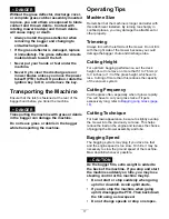
Страница 14: ...airs while the engine is running Engage the parking brake WARNING Without the grass deflector bagger tubes or complete bagger assembly mounted in place you and others are exposed to blade contact and thrown debris Contact with the rotating mower blade s impeller and thrown debris will cause injury or death Always install the grass deflector when removing the bagger and changing to side discharge m...

Страница 15: ...l when lifting or handling a grass bag that is full 1 Disengage the PTO move the motion control levers to the NEUTRAL LOCK position and engage the parking brake 2 Shut off the engine remove the key and wait for all moving parts to stop before leaving the operating position 3 Unlatch the bagger latch 4 Open the bagger hood 5 Compress the debris into the bags With both hands lift up on the bag and u...

Страница 16: ... open 9 Use a stick or similar object not your hands to remove and clear the obstruction from the blower assembly 10 After you remove the obstruction close the blower assembly so that the handle latches Removing the Bagger WARNING Components around the engine will be hot if the machine has been running Touching hot components can cause burns Do not touch engine components when hot Allow the engine...

Страница 17: ...with the left side of the mower Do not trim with the right side of the mower because you could damage the bagger chute and discharge tube Cutting Height For optimum bagging performance set the deck height of cut to remove no more that 51 to 76 mm 2 to 3 inches or 1 3 of the grass height whichever is less Cutting off more than this reduces the capacity of the vacuum system Cutting Frequency Cut the...

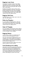
Страница 18: ...ns of Plugging As you are bagging a small amount of grass clippings normally blow out the front of the mower An excessive amount of clipping blow out indicates that the bagger is full or the blower or tube is plugged Bagging Blades In most mowing conditions the standard high lift blades provide the best bagging performance Use a Toro Atomic blade for bagging leaves in dry conditions In dry dusty c...

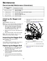
Страница 19: ...s let them dry thoroughly Note With all parts installed start and run the machine for a minute to assist in drying Inspecting the Bagger Belt Service Interval After the first 8 hours Every 25 hours Check belts for cracks frayed edges burn marks or any other damage Replace damaged belts Replacing the Bagger Belt 1 Disengage the PTO move the motion control levers to the NEUTRAL LOCK position and eng...

Страница 20: ...Replace these parts if they are cracked or broken 4 Check the bags bagger frame and screen Replace any parts that are cracked or broken 5 Tighten all nuts bolts and screws Inspecting the Mower Blades 1 Inspect the mower blades regularly and whenever a blade strikes a foreign object 2 If blades are badly worn or damaged install new blades Refer to the Operator s Manual for the machine for complete ...

Страница 21: ...r to Inspecting the Bagger page 20 3 Make sure that the bags are empty and thoroughly dry 4 Check the belt for wear or cracks 5 Store the machine in a clean dry place out of direct sunlight If you must store the machine outside cover it with a weatherproof cover This protects the plastic parts and extends the life of the machine 21 ...

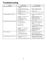
Страница 22: ... The bags are too full 1 Empty the bags more frequently 2 The engine speed is low 2 Always operate the bagger at full throttle 3 Grass is too wet 3 Cut the grass when it is dry 4 Grass is too long 4 Cut no more than 51 to 76 mm 2 to 3 inches or 1 3 of the grass height whichever is less 5 The screen in the bagger hood is plugged 5 Remove debris leaves or grass clippings from the screen 6 The ground...

Страница 23: ...led as required per Part B of Annex VII of 2006 42 EC We will undertake to transmit in response to requests by national authorities relevant information on this partly completed machinery The method of transmission shall be electronic transmittal This machinery shall not be put into service until incorporated into approved Toro models as indicated on the associated Declaration of Conformity and in...

Страница 24: ...r you may contact any Toro Authorized Distributor to arrange service Visit http www toro com to locate a Toro distributor in your area 2 Bring the product and your proof of purchase sales receipt to the Service Dealer 3 If for any reason you are dissatisfied with the Service Dealer s analysis or with the assistance provided contact us at Toro Warranty Company 8111 Lyndale Avenue South Bloomington ...

Отзывы: