background image

EN-5

Assembly

Note:

Determine left and right sides of
snowthrower by standing in the normal
operating position.

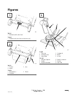
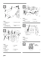
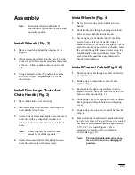
Install Wheels (Fig. 2)

1.

Place a wood block under the wheel axle for
support.

2.

Slide a spacer and wheel onto the axle. The side
of the wheel with six spokes must face the center
of the axle. Slide a pushnut onto the end of the
axle.

3.

Using a hammer, strike the pushnut to seat the
nut firmly in place. Repeat steps 2–3 for the
other wheel.

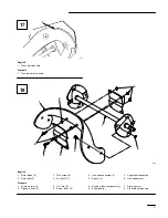
Install Discharge Chute And
Chute Handle (Fig. 3)

1.

Place chute handle over chute ring.

2.

Insert discharge chute between chute ring and
chute handle. Align holes.

3.

Secure back of chute and handle to center hole in
chute ring with a carriage bolt, washer, and
locknut. Position washer and nut on outside of
chute.

Note:

Chute ring may be rotated to ease
assembly of discharge chute.

4.

Secure chute and handle to remaining holes in
chute ring and tighten all nuts securely.

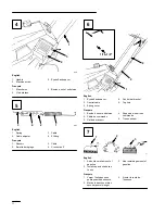
Install Handle (Fig. 4)

1.

Remove tie securing control cable to lower
handle.

2.

Slide handle ends through openings in shroud
and onto lower handles inside shroud.

3.

Secure right side of handle with (2) machine
screws. Secure left side of handle with (1)
machine screw, (1) eyebolt, and a spacer. Use the
eyebolt to mount upper left side of handle. Insert
the eyebolt through the spacer before using it to
secure handle to the snowthrower frame. The
eyebolt must be positioned perpendicular to
handle when tightened.

Install Control Cable (Fig. 5-6)

1.

Route control cable through eyebolt on left side
of snowthrower.

2.

Hook spring to round hole at end of cable
adjuster (Fig. 5).

3.

Route cable through elongated hole in cable
adjuster. Insert Z fitting on end of cable into 3rd
hole on cable adjuster (Fig. 5).

4.

Slide spring cover over spring and cable adjuster.
Push spring end through hole at end of spring
cover.

5.

Hook spring into top hole of control bar bracket
(Fig. 6).

6.

Move control bar back toward handle until slack
in cable is removed. The gap between the control
bar bracket and handle should be approximately
1/16”–1/8”. See insert, Figure 6. If an
adjustment is required, refer to Adjusting
Control Bar, page 10.

Note:

The control cable must always have
slack in it when in the disengaged
position.

Содержание CCR 1000 38400

Страница 1: ...Manual Manuel de l Utilisateur FORM NO 3321 375 CCR 1000 Snowthrower Model No 38400 9900001 Up Model No 38405 9900001 Up CCR 1000 Déneigeuse Modèle No 38400 9900001 et suivants Modèle No 38405 9900001 et suivants ...

Страница 2: ...ause cancer birth defects or other reproductive harm WARNING Les gaz d échappement de cette machine contiennent des produits chimiques reconnus dans l Etat de Californie comme étant cancérigènes responsables de malformations congénitales et dangereux pour les organes reproducteurs AVERTISSEMENT ...

Страница 3: ...uméros de modèle et de série 894 1 3 2 English 1 Pushnut 2 Spacer 3 Axle Français 1 Écrou poussoir 2 Entretoise 3 Essieu 895 1 4 6 5 2 3 English 1 Chute ring 2 Discharge chute 3 Chute handle 4 Carriage bolt 5 Washer 6 Locknut Français 1 Couronne d éjecteur 2 Ejecteur 3 Poignée d orientation 4 Boulon de carrossier 5 Rondelle 6 Ecrou frein 1 2 3 ...

Страница 4: ...Eyebolt and spacer 2 Control cable 3 Spring cover 4 Control bar bracket 5 Top hole Français 1 Boulon à oeil et entretoise 2 Câble de commande 3 Garde du ressort 4 Support de la barre de commande 5 Trou supérieur 111 1 2 3 English 1 Add oil to small amount of gasoline 2 Install cap and shake can to mix 3 Add remaining amount of gasoline Français 1 Verser l huile dans une petite quantité d essence 2...

Страница 5: ...6 Raccord du cordon MODÈLE À DÉMARRAGE ÉLECTRIQUE 899 3 1 2 English 1 Chute handle 2 Chute deflector handle 3 Deflector mounting nuts Français 1 Poignée d orientation de l éjecteur 2 Poignée du déflecteur 3 Écrous de montage du déflecteur 900 901 1 1 16 English 1 Scraper Français 1 Lame racleuse 902 2 1 English 1 Scraper 2 Carriage bolt flange nut Français 1 Lame racleuse 2 Boulon de carrossier et...

Страница 6: ...ondelle 903 4 5 3 2 1 English 1 Engine pulley 2 Idler pulley 3 Brake arm 4 Rotor pulley 5 Belt Français 1 Poulie du moteur 2 Poulie folle 3 Bras de frein 4 Poulie du rotor 5 Courroie m 2578 1 2 English 1 Control panel 2 Capscrews Français 1 Panneau de commande 2 Boulons à tête m 2580 1 English 1 Spark plug wire Français 1 Fil de bougie 110 0 030 0 76 mm 12 13 14 15 16 ...

Страница 7: ...sh 1 Rotor blade 2 2 Rotor half 2 3 Torx screw 8 4 Locknut 13 5 Hex head capscrew 4 6 Spacer 4 7 Auger shaft assembly 8 Hex head screw Français 1 Lame du rotor 2 2 Plaque d acier 2 3 Vis Torx 8 4 Écrou frein 13 5 Boulon à tête hexagonale 4 6 Entretoise 4 7 Arbre du rotor 8 Vis à tête hexagonale 17 18 ...

Страница 8: ...vi 681 English 1 Thin side 2 Thick side 3 Wear indicator hole Français 1 Côté mince 2 Côté épais 3 Trou indicateur d usure 19 ...

Страница 9: ...rs in the space below Model No Serial No Read this manual carefully to learn how to operate and maintain your product correctly Reading this manual will help you and others avoid personal injury and damage to the product Although Toro designs produces and markets safe state of the art products you are responsible for using the product properly and safely You are also responsible for training perso...

Страница 10: ...ecal is illegible or damaged repair or replace it before beginning operation Also tighten any loose nuts bolts or screws 6 Wear adequate winter clothing and rubber boots that will ensure proper footing on slippery surfaces Do not wear loose fitting clothing that could possibly get caught in moving parts 7 Always wear safety glasses or eye shields during operation or while performing an adjustment ...

Страница 11: ...ark plug wire and keep the wire away from the plug to prevent someone from accidentally starting the unit 23 WHENEVER YOU LEAVE THE OPERATING POSITION STOP ENGINE BY TURNING KEY TO OFF REMOVE KEY FROM SWITCH IF UNIT WILL BE UNATTENDED 24 Let snowthrower run for a few minutes after clearing snow so moving parts do not freeze Maintaining Snowthrower 25 REMOVE KEY FROM SWITCH when storing snowthrower...

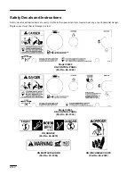
Страница 12: ... the operator and are located near any area of potential danger Replace any decal that is damaged or lost Model 38400 ON CONTROL PANEL Part No 88 1020 ON DISCHARGE CHUTE Part No 94 2900 Model 38405 ON CONTROL PANEL Part No 88 1030 ON MUFFLER GUARD Part No 95 1904 ON HANDLE Part No 66 6870 ...

Страница 13: ... handle ends through openings in shroud and onto lower handles inside shroud 3 Secure right side of handle with 2 machine screws Secure left side of handle with 1 machine screw 1 eyebolt and a spacer Use the eyebolt to mount upper left side of handle Insert the eyebolt through the spacer before using it to secure handle to the snowthrower frame The eyebolt must be positioned perpendicular to handl...

Страница 14: ...is not necessary 1 APPROVED OIL For simplicity and best engine performance mix the contents of one 5 2 ounce bottle of Toro 50 1 Two Cycle Oil with two gallons of fresh unleaded regular gasoline You can also use Toro Easy Mix Two Cycle Oil 3 2 ounce bottle mixed one per gallon of gasoline 40 1 ratio in this Toro two cycle engine Leaded regular gasoline may be used if unleaded regular is not availa...

Страница 15: ...HAS BEEN RUNNING AND IS HOT Note When starting engine for first time or after running out of fuel more priming may be required to start engine 4 STARTING A RECOIL STARTING Hold snowthrower with one hand and pull recoil starter vigorously with other hand If engine does not start after three pulls push primer once more and pull recoil starter vigorously again B ELECTRIC STARTING Connect extension co...

Страница 16: ...oreign objects which may be picked up and thrown by the rotor blades Such items could be covered by snowfall and therefore unnoticed until struck by the rotor blades Always be sure to keep children and pets away from area of operation POTENTIAL HAZARD Stones toys and other foreign objects may be picked up and thrown by the rotor blades WHAT CAN HAPPEN Thrown objects can cause serious personal inju...

Страница 17: ...re new scraper to housing with carriage bolts and flange nuts Position heads of bolts inside housing Replacing Drive Belt Fig 12 13 After extended use the drive belt may wear and require replacement If after adjusting the control bar the drive belt continues to slip under a heavy load or the rotor does not turn check to see if the belt is severely worn 1 Turn ignition key to OFF 2 Drain gasoline f...

Страница 18: ...termined by the running time and the roughness of the driveway or sidewalk Removing Old Blade 1 Remove 4 torx screws and 4 locknuts securing outer edges of rotor blade to rotor shaft assembly Fig 18 2 Next remove 2 hex head capscrews spacers and locknuts securing center of blade to steel plates Fig 18 3 Loosen the hex head screw securing the rotor halves to the auger shaft assembly Fig 18 4 Slide ...

Страница 19: ...gine until it will not restart Dispose of fuel properly Recycle per local codes DO NOT store STABILIZED gasoline over 90 days 2 CYLINDER PISTON CARE Slowly pull recoil starter until resistance is felt due to compression pressure then stop Release starter tension slowly to prevent engine from reversing due to compression pressure This position closes both the intake and exhaust ports which prevents...

Страница 20: ... Your State Law Relate To This Warranty There is no other express warranty except for special emission system coverage on some products and the TORO Starting Guarantee on GTS Engines This express warranty does not cover D Cost of regular maintenance service or parts such as filters fuel lubricants tuneĆup parts blade sharpening brake and clutch adjustments D Any product or part which has been alte...

Страница 21: ...résentant du service après vente à vous fournir des informations précises sur votre machine Les numéros de modèle et de série de l appareil sont indiqués sur une décalcomanie comme illustré à la figure 1 A titre de référence notez les numéros de modèle et de série du produit dans l espace ci dessous No de modèle No de série Lisez attentivement ce manuel pour vous familiariser avec l utilisation et...

Страница 22: ...t arrêter la machine et débrayer rapidement toutes les commandes 2 Ne laissez jamais un enfant manier la déneigeuse L utilisation de la déneigeuse doit être réservée à des adultes ayant pris connaissance du contenu de ce manuel 3 Ne laissez personne en particulier les enfants et les animaux approcher de la déneigeuse ou de la zone de travail 4 Inspectez soigneusement la zone à déblayer et enlevez ...

Страница 23: ...nte 17 N UTILISEZ JAMAIS LA DENEIGEUSE SUR UN TOIT 18 Ne surchargez pas la déneigeuse en essayant de travailler trop vite 19 Sur des surfaces glissantes n utilisez pas la vitesse maximum de déplacement 20 Soyez très prudent lorsque vous traversez ou déblayez des trottoirs des routes ou des allées empierrées ou couvertes de gravier Suivez les Conseils d utilisation de la page 8 au point 4 21 Si la ...

Страница 24: ... remisage qui figurent dans ce manuel avant de remiser la déneigeuse pour une durée prolongée afin de n oublier aucune opération importante 28 N effectuez que les opérations d entretien décrites dans le manuel Avant toute opération d entretien retirez la clé de contact pour éviter les risques de démarrage accidentel Si vous avez besoin de grosses réparations adressez vous à un réparateur agréé de ...

Страница 25: ...e tous les endroits potentiellement dangereux Remplacer toute décalcomanie endommagée ou manquante Modèle 38400 SUR LE PANNEAU DE COMMANDE Réf no 88 1020 SUR L EJECTEUR Réf no 94 2900 Modèle 38405 SUR LE PANNEAU DE COMMANDE Réf no 88 1030 SUR LA GARDE DU SILENCIEUX Réf no 95 1904 SUR LE MANCHERON Réf no 66 6870 ...

Страница 26: ... Glisser les extrémités du mancheron dans les ouvertures prévues dans le capot et sur le mancheron inférieur à l intérieur du capot 3 Fixez le côté droit du mancheron à l aide de deux 2 vis à métal et le côté droit au moyen d une 1 vis à métal d un 1 boulon à oeillet et d une rondelle Utilisez le boulon à oeillet pour monter la partie supérieure gauche du mancheron Insérez le boulon à oeillet dans...

Страница 27: ...s sont équipés des systèmes anti pollution suivants EM TWC si applicable Ils ne comprennent pas de fonctions réglables par l utilisateur et ne demandent donc plus aucun réglage Préparation du mélange essence huile Fig 7 Utiliser de l essence sans plomb propre et fraîche éventuellement oxygénée ou reformulée avec un taux d octane de 85 ou plus Pour garantir la fraîcheur de l essence ne pas faire de...

Страница 28: ...e Remarque Les stabilisateurs conditionneurs sont plus efficaces lorsqu on les mélange à de l essence fraîche Important NE JAMAIS UTILISER DE METHANOL D ESSENCE CONTENANT DU METHANOL D ESSENCE CONTENANT PLUS DE 10 D ETHANOL D ESSENCE SUPER OU D ESSENCE BLANCHE CES PRODUITS POURRAIENT ENDOMMAGER LE SYSTEME D ALIMENTATION NE PAS UTILISER D ADDITIFS AUTRES QUE CEUX CONÇUS POUR LA STABILISATION DU CAR...

Страница 29: ...ourant standard Pousser le bouton du démarreur Quand le moteur a démarré débrancher le cordon des deux côtés Important Un usage prolongé peut endommager le démarreur pour cause de surchauffe Si l on a du mal à démarrer NE PAS REPETER LA PROCEDURE SUIVANTE PLUS DE DEUX FOIS Actionner le démarreur selon un rythme de 5 secondes de marche 5 secondes d arrêt pas plus de 10 fois d affilée Si le moteur n...

Страница 30: ...ppent Ne jamais laisser les enfants ou les animaux approcher lorsqu on utilise la machine DANGER POTENTIEL Des pierres des jouets ou d autres objets peuvent être ramassés et projetés par les lames du rotor QUELS SONT LES RISQUES Des objets projetés peuvent blesser sérieusement l utilisateur ou des personnes à proximité COMMENT SE PROTEGER Ne pas laisser d objets susceptibles d être ramassés et pro...

Страница 31: ...u caractère plus ou moins abrasif des surfaces déneigées 1 Tourner la clé de contact en position d arrêt OFF 2 Vidanger le réservoir d essence voir page 9 3 Basculer la déneigeuse debout sur l avant 4 Retirer les 3 boulons de carrossier et les 3 écrous à embase de fixation de la lame racleuse Fig 11 et déposer la lame racleuse 5 Monter une nouvelle lame racleuse et la fixer au carter à l aide des ...

Страница 32: ...gie et la retirer Inspecter la bougie et la remplacer si elle est fissurée ou encrassée NE PAS NETTOYER OU DECAPER LA BOUGIE AU SABLE OU A LA TOILE EMERI VU LE RISQUE D ENDOMMAGER LE MOTEUR PAR L INTRODUCTION DANS LE CYLINDRE DE PARTICULES TOMBEES DE LA BOUGIE 3 MONTAGE DE LA BOUGIE Régler l écartement des électrodes Fig 16 à 0 76 mm Mettre la bougie en place et la serrer à 20 4 N m Si l on n a pa...

Страница 33: ...ns placer la tête des vis du côté épais de la lame Serrer solidement tous les écrous vis et boulons Réglage de la barre de commande Fig 5 et 6 Contrôler périodiquement le réglage de la barre de commande 1 Tourner la clé de contact en position d arrêt OFF 2 CONTROLE DU RÉGLAGE Ramener la barre de commande vers l arrière en direction du mancheron jusqu à ce que le câble soit tendu L écart entre le s...

Страница 34: ...n et d échappement ce qui protège l alésage du cylindre de la corrosion 3 NETTOYAGE ET RESSERRAGE DE LA VISSERIE Resserrer les vis les boulons et les écrous si nécessaire Réparer ou remplacer les pièces endommagées Nettoyer à fond la machine 4 RANGEMENT Couvrir la déneigeuse et la ranger dans un endroit propre et sec hors de portée des enfants NE JAMAIS RANGER LA DENEIGEUSE DANS UNE PARTIE HABITEE...

Страница 35: ...duits et la garantie de démarrage TORO pour les moteurs GTS Cette garantie expresse ne couvre pas D Les frais normaux d entretien et de remplacement de pièces telles que les filtres le carburant les lubrifiants les pièces d usure l affûtage des lames ou le réglage des freins et de l embrayage D Les produits ou pièces ayant subi des modifications ou un usage abusif ou nécessitant un remplacement ou...

Страница 36: ......
Отзывы: