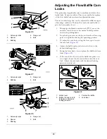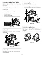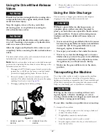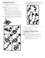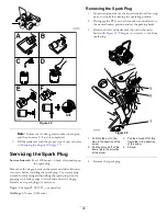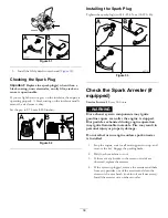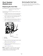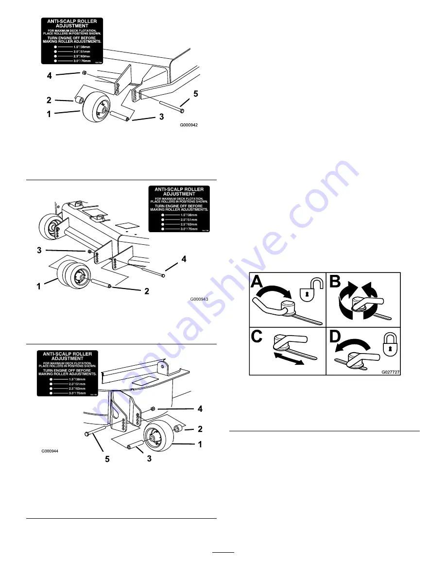
Figure 26
1.
Anti-scalp roller
4.
Flange nut
2.
Spacer
5.
Bolt
3.
Bushing
Figure 27
1.
Anti-scalp roller
3.
Flange nut
2.
Bushing
4.
Bolt
Figure 28
1.
Anti-scalp roller
4.
Flange nut
2.
Spacer
5.
Bolt
3.
Bushing
Adjusting the Flow Baffle Cam
Locks
This procedure is applicable only to machines with the flow
baffle locks. Certain models will have nuts and bolts in-place
of the flow baffle locks and can be adjusted the same.
The mower discharge flow can be adjusted for different types
of mowing conditions. Position the cam locks and baffle to
give the best quality of cut.
1.
Disengage the blade control switch (PTO), move the
motion control levers to the neutral locked position,
and set the parking brake.
2.
Stop the engine, remove the key, and wait for all moving
parts to stop before leaving the operating position.
3.
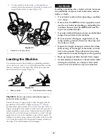
To adjust the cam locks, swing the lever up to loosen
the cam lock (
4.
Adjust the baffle and cam locks in the slots to the
desired discharge flow.
5.
Swing the lever back over to tighten the baffle and cam
locks (
).
6.
If the cam locks do not lock the baffle into place or it
is too tight, loosen the lever and then rotate the cam
lock. Adjust the cam lock until the desired locking
pressure is achieved.
Figure 29
1.
Unlock lever
3.
Position the baffle
2.
Rotate the cam lock to
increase or decrease
locking pressure
4.
Lock lever
25
Содержание 74955
Страница 65: ...Schematics G020788 Electrical Schematic Rev A 65 ...
Страница 66: ...Notes 66 ...
Страница 67: ...Notes 67 ...


