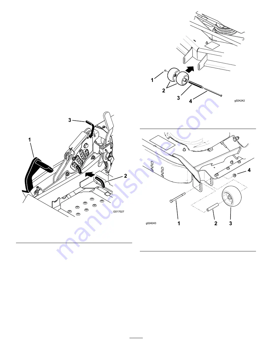
Adjusting the Height-of-cut Pin
The height of cut is adjusted from 25 to 140 mm (1 to
5-1/2 inches) in 6 mm (1/4 inch) increments by moving the
clevis pin into different hole locations.
1.
Move the transport lock to the lock position.
2.
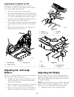
Push on the deck-lift pedal with your foot and raise the
mower deck to the transport position (also the 140 mm
(5-1/2 inch) cutting-height position); refer to Figure 27.
3.
To adjust, rotate the pin 90 degrees and remove the pin
from the height-of-cut bracket (Figure 27).
4.
Select a hole in the height-of-cut bracket corresponding
to the height of cut desired, and insert the pin (Figure
27).
5.
Push on the deck lift, pull back on the transport lock,
and slowly lower the mower deck.
1
3
2
G017027
Figure 27
1.
Deck-lift pedal
3.
Transport lock
2.
Height-of-cut pin
Adjusting the Anti-scalp
Rollers
Whenever you change the height of cut, it is recommended to
adjust the height of the anti-scalp rollers.
1.
Disengage the blade-control switch (PTO), move the
motion-control levers to the neutral-locked position
and set the parking brake.
2.
Stop the engine, remove the key, and wait for all moving
parts to stop before leaving the operating position.
3.
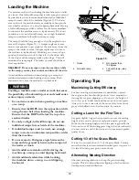
Adjust the anti-scalp rollers as shown in Figure 28 and
Figure 29 to match the closest height-of-cut position.
g024242
1
2
3
4
Figure 28
1.
Flange nut
3.
Bushing
2.
Anti-scalp roller
4.
Bolt
g024243
1 2 3
4
Figure 29
1.
Bolt
3.
Anti-scalp roller
2.
Bushing
4.
Flange Nut
Adjusting the Skid(s)
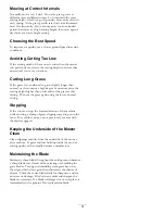
Mount the skids in the lower position when operating in
height of cuts higher than 64 mm (2-1/2 inches) and in the
higher position when operating in height of cuts lower than
64 mm (2-1/2 inches).
Note:
When the skids become worn, switch the skid to the
opposite sides of the mower, flipping them over. This will
allow you to use the skids longer before replacing them.
1.
Disengage the PTO and set the parking brake.
27
Содержание 74942TE
Страница 68: ...Schematics Wire Diagram Rev A 68 ...
Страница 69: ...Notes 69 ...
Страница 70: ...Notes 70 ...

