


G010233
1
2
3
4
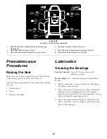
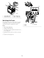
Figure 26
1.
Anti-scalp roller
3.
Flange Nut
2.
Bolt
4.
Hole spacing
Positioning the Seat
The seat can move forward and backward. Position the
seat where you have the best control of the machine
and are most comfortable.
While sitting in the operator’s position, raise the seat
adjustment lever slightly and move the seat forward or
backward to the desired position (Figure 27).
G010016
G010232
1
Figure 27
1.
Adjustment lever
Changing the Seat Ride
Suspension
The number of seat springs can be changed to
maximize rider comfort. More springs should be used
with heavier operators and on rough terrain. Fewer
springs should be used with lighter operators and when
mowing smooth, well established lawns. Always keep
the number of springs on the left and right side the
same when adding and removing springs.
G010484
4
4
Figure 28
1.
Bolt
3.
Nut
2.
Spring
4.
Additional mounting holes
Up to five springs can be secured to the seat support
with a nut and bolt, see Figure 28.
Refer to your Parts Manual for spring and hardware
part numbers.
Adjusting the Motion Control
Levers
Adjusting the Height
The motion control levers can be adjusted higher or
lower for maximum operator comfort.
1. Remove the 2 bolts holding the control lever to the
control arm shaft (Figure 29).
2. Move the control lever to the next set of holes.
Secure the lever with the 2 bolts (Figure 29).
Note:
The control levers can also be installed on
the outside of the control arm shafts.
23
Содержание 74833
Страница 50: ...Schematics G012083 Wire Diagram Rev B 50...
Страница 51: ...Notes 51...