Toro 41440 Скачать руководство пользователя страница 12

12

ENGINE LUBRICATION:

IMPORTANT! AFTER THE INITIAL RUN-IN

PERIOD (APPROXIMATELY 5 HOURS) AND

EVERY 25 HOURS THEREAFTER.

1.

Change the oil in the engine’s crankcase.

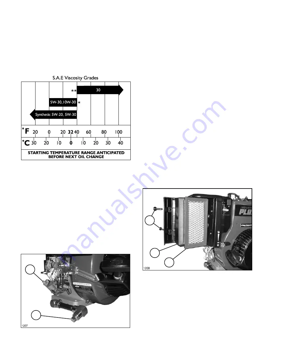
Change oil while the engine is warm.  Refill with

new oil as recommended in the chart below.

ENGINE MAINTENANCE

* Air cooled engines run hotter than automotive

engines.  Use of multi-viscosity oils (10W-30, etc.)

above 40 F (4 C) will result in high oil consumption

and possible engine damage.  Check oil more

frequently if using these type oils.

** SAE 30 oil, if used below 40°F (4°C) will result

in hard starting and possible engine bore damage

due to inadequate lubrication.

Oil Capacity:  Approximately 44 ounces or 1.3

liters.

2.

Remove the pipe plug in the end of the oil drain

pipe and let oil flow into a drain pan.  When oil

stops, reinstall drain plug.  See FIG. 2.

FIG. 2

1. Oil Fill

2. Drain Plug

AFTER EVERY 5 HOURS OR DAILY:

1.

Check the oil level in the engine’s crankcase

before engine start-up, while engine is cool.  Have

the machine on a level surface.

2.

Clean the area around the oil/fill check plug

and remove it.

3.

The level should be up to but not over, the point

of overflowing the filler neck.

4.

If the level is low, add API “service

classification” SE, SF or SG.  See viscosity chart

for the recommended weight.

5.

Reinstall the oil fill/check plug and tighten

securely.  Make sure it is tightened to 13 ft. lbs.

(17.6 Nm) torque.

IMPORTANT!  Keep the area around the fill tube

clean, to prevent dirt from falling into the engine.
AIR CLEANER:

Clean the  Pre-Cleaner after every 25 hours of

operation.  Clean more often in extreme dusty or

dirty conditions.  Replace air cleaner parts if very

dirty.
1. Loosen Cover Screws and remove Cover,

Pre-Cleaner and Cartridge. See FIG. 3.

2. Wash Pre-Cleaner in liquid detergent and

water. Squeeze dry in clean cloth. Saturate in

engine oil. Squeeze in clean, absorbent cloth to

remove ALL EXCESS oil. If very dirty or damaged,

replace it.
3. Clean Cartridge by tapping gently on flat

surface. If very dirty or damaged, replace it. Do

NOT oil Cartridge.
4. Replace Cartridge, Pre-Cleaner and Cover.

Secure Cover with the (2) Cover Screws.

FIG. 3

1. Cover Screws

3. Cartridge

2. Pre-Cleaner

1

3

2

2

1

1205

Содержание 41440

Страница 1: ...SPRAYING 6 NOZZLE SELECTION CHARTS 7 8 STORAGE 9 ENGINE 10 13 BEFORE OPERATING 10 OPERATING INSTRUCTIONS 11 MAINTENANCE 12 13 STORAGE 13 41441 CENTRIFUGAL PUMP 14 19 CONTROLS 14 BEFORE SPRAYING 15 OP...

Страница 2: ...operator s personal safety as well as those persons in the work area will depend on the careful actions and good judgement of the operator To reduce the potential for injury or death comply with the...

Страница 3: ...ave stopped C Shut off the Skid Sprayer s engine and remove wire from spark plug Make sure wire cannot contact plug accidentally D Keep hands feet and clothing away from all power driven parts 2 Keep...

Страница 4: ...ompany 8111 Lyndale Ave South Date Purchased ___________ Minneapolis MN 55420 SPARK ARRESTOR When the machine is used or operated on any California forest brush or grass covered land a properly operat...

Страница 5: ...ND MODEL AND SERIAL NUMBERS TO THE TORO CO 8111 LYNDALE AVE S MPLS MN 55420 65 3090 TRAILER WEIGHT LBS SKID WEIGHT LBS 110 100 90 80 70 60 50 1385 1300 1220 1135 1050 965 885 1620 1535 1455 1370 1285...

Страница 6: ...00 sq ft Vehicle Speed 4 M P H Nozzle Spacing 20 inches 1 70 G P K x 4 M P H x 20 1 00 G P M 137 per nozzle EXAMPLE SI FORMULA Application Rate 907 lit hectare Vehicle Speed 5 km h Nozzle Spacing 50 c...

Страница 7: ...allons per 1000 Sq Ft at 20 Spacings GPM Color Code 2 5 MPH 3 MPH 3 5 MPH 4 MPH 4 5 MPH 5 MPH 5 5 MPH 6 MPH 20 0 14 0 38 0 32 0 27 0 24 0 21 0 19 0 17 0 16 95 9221 Yellow 30 0 17 0 46 0 39 0 33 0 29 0...

Страница 8: ...176 275 1 89 567 454 378 324 284 252 227 206 350 2 13 639 511 426 365 320 284 256 232 150 1 67 501 401 334 286 251 223 200 182 95 9224 Grey 200 1 93 579 463 386 331 290 257 232 211 275 2 27 681 545 45...

Страница 9: ...alf water or fill pump with FLUID FILM and then drain it A protective coating of FLUID FILM will remain on the inner pump surfaces Save the excess FLUID FILM for the next application Plug the ports to...

Страница 10: ...engine is operated in dusty or dirty conditions WARNING Because gasoline is flammable caution must be used when storing or handling it Do not fill fuel tank while engine is running hot or when machine...

Страница 11: ...ntrol to the RUN position after the engine starts and warms up See FIG 2 For a Warm Engine normal operating temperatures Place the throttle control to the fast positions Move the Choke Control to the...

Страница 12: ...ine on a level surface 2 Clean the area around the oil fill check plug and remove it 3 The level should be up to but not over the point of overflowing the filler neck 4 If the level is low add API ser...

Страница 13: ...N AIR INTAKE COOLING AREAS To insure proper cooling make sure the screen cooling fins and other external surfaces of the engine are kept clean at all times NOTE Operating the engine with a blocked scr...

Страница 14: ...FIG 5 1 Pump Engagement 4 Suction Valve Handle Lever open 2 Pump Engagement 5 Bleed Valve Release Lever 6 Optional Spray Gun 3 Agitator Valve Handle Valve Handle closed open RATCHET VALVE HANDLE Open...

Страница 15: ...s entire procedure should be repeated whenever changing operating pressure nozzles speed chemical etc FILLING THE SOLUTION TANK WARNING CHEMICALS ARE HAZARDOUS AND CAN CAUSE PERSONAL INJURY Carefully...

Страница 16: ...r should be accomplished in an area where there is no potential for the chemicals to be washed off in surface water or to enter subsurface drainage systems When Sprayer is not to be used for an extend...

Страница 17: ...material to flow through the nozzle can cause an expensive loss in chemical and or turf damage SUCTION STRAINER Turn off Suction Line Valve if Tank is full of spray solution Remove the cap and clean...

Страница 18: ...aned and flushed grooved 3 Carbon washer worn Seal improperly installed Check installation instructions for proper assembly unevenly 4 Rubber bellows of Did pump run dry or cavitate Check to insure se...

Страница 19: ...o remove rust and corrosion particles Seal Replacement Pump Housing Reassembly NOTE Reassemble if drive end is not to be repaired Be extremely careful with the new seal Take special care not to scratc...

Страница 20: ...phragm Pump Liquids under high pressure are dangerous WARNING Loss of control of the transport vehicle can cause serious injury to operator or bystanders Never use Spray Gun from operator s seat while...

Страница 21: ...ition 2 Pressure Gauge 5 Optional Boom Valve 3 Fine Adj Knob Closed 6 Pressure Adj Notches 1 5 2 4 FIG 12 1 Left Boom Shutoff 2 Right Boom Shutoff Valve open Valve open LEFT BOOM SHUTOFF VALVE HANDLE...

Страница 22: ...e number three position the pressure is about 450 PSI D In the number four position the pressure is about 550 PSI WARNING Fluids under high pressure can cause severe injury NEVER USE DIAPHRAGM PUMP WH...

Страница 23: ...chemically neutralize the liquid pumped Mix according to the chemical manufacturer s directions This will dissolve most residue remaining in the pump leaving the inside of the pump clean for the next...

Страница 24: ...17 mm box wrench to remove manifold nuts With manifold removed valves can readily be removed and checked for debris or wear 2 To replace valves or O Rings see your TORO Dealer for the appropriate kit...

Страница 25: ...Adjust Valve Handle Handle 2 Pressure Gauge AGITATOR VALVE HANDLE Opens and closes the Agitator Valve to activate adjust or stop the agitation of the spray solution in the Tank SUCTION VALVE HANDLE O...

Страница 26: ...als Instructions on chemical manufacturer s container labels regarding mixing proportions should be read and strictly followed Keep spray material from skin If spray material comes in contact with bod...

Страница 27: ...the most common causes for faulty pump performance is gumming or corrosion inside the pump Flush the pump and entire system with a solution that will chemically neutralize the liquid pumped Mix accor...

Страница 28: ...and flushed grooved 3 Carbon washer worn Seal improperly installed Check installation instructions for proper assembly unevenly 4 Rubber bellows of Did pump run dry or cavitate Check to insure seal c...

Страница 29: ...nk to remove rust and corrosion particles Seal Replacement Pump Housing Reassembly NOTE Reassemble if drive end is not to be repaired Be extremely careful with the new seal Take special care not to sc...

Страница 30: ...30 Helping you put quality into...

Страница 31: ...31 Helping you put quality into...

Страница 32: ...substitute Product or service during periods of malfunc tion or non use Some states do not allow the exclusion of incidental or consequential damages so the above exclusion may not apply to you Note t...

Отзывы: