background image

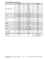
U.S. to Metric Conversions

To Convert

Into

Multiply By

Miles

Kilometers

1.609

Yards

Meters

0.9144

Feet

Meters

0.3048

Feet

Centimeters

30.48

Inches

Meters

0.0254

Inches

Centimeters

2.54

Linear Measurement

Inches

Millimeters

25.4

Square Miles

Square Kilometers

2.59

Square Feet

Square Meters

0.0929

Square Inches

Square Centimeters

6.452

Area

Acre

Hectare

0.4047

Cubic Yards

Cubic Meters

0.7646

Cubic Feet

Cubic Meters

0.02832

Volume

Cubic Inches

Cubic Centimeters

16.39

Tons (Short)

Metric Tons

0.9078

Pounds

Kilograms

0.4536

Weight

Ounces

Grams

28.3495

Pressure

Pounds/Square Inch

Kilopascal

6.895

Foot-Pounds

Newton-Meters

1.356

Foot-Pounds

Kilogram-Meters

0.1383

Work

Inch-Pounds

Kilogram-Centimeters

1.152144

Quarts

Liters

0.9463

Liquid Volume

Gallons

Liters

3.785

Liquid Flows

Gallons/Minute

Liters/Minute

3.785

1. Subtract by 32°

Temperature

Fahrenheit

Celsius

2. Multiply by 5/9

POWER CLEAR® 721/821 Snowthrower Service Manual

Page 2–9

Specifications and Maintenance: Torque Specifications

3438-776 Rev A


Содержание 38754

Страница 1: ...76 Rev A POWER CLEAR 721 821 Snowthrower Service Manual Published July 2020 2020 The Toro Company 8111 Lyndale Avenue South Bloomington MN 55420 Original Instructions EN Contact us at www Toro com All Rights Reserved ...

Страница 2: ...Revision History Revision History Page 2 POWER CLEAR 721 821 Snowthrower Service Manual 3438 776 Rev A ...

Страница 3: ...topics covered in this manual We are hopeful that you will find this manual a valuable addition to your service shop If you have any questions or comments regarding this manual please contact us at the following address The Toro Company RLC SWS Customer Care Department 8111 Lyndale Avenue South Bloomington MN 55420 The Toro Company reserves the right to change product specifications or make change...

Страница 4: ...ening sequence Component orientation that may not be obvious Critical Torque This icon is used to highlight an assembly torque requirement that is different than what is recommended in the Standard Torque Tables Fluid Specifications This icon is used to highlight fluid specifications and capacities that are less common and may not appear on the machine service decal or in the machine Operator s Ma...

Страница 5: ...ons 2 3 Chapter 3 Troubleshooting 3 1 General Troubleshooting 3 3 Chapter 4 Engine 4 1 General Information 4 2 Service and Repairs 4 3 Chapter 5 Chassis 5 1 General Information 5 2 Service and Repairs 5 3 Chapter 6 Drive System 6 1 General Information 6 2 Service and Repairs 6 3 POWER CLEAR 721 821 Snowthrower Service Manual Page 5 Preface 3438 776 Rev A ...

Страница 6: ...Preface Page 6 POWER CLEAR 721 821 Snowthrower Service Manual 3438 776 Rev A ...

Страница 7: ...Chapter 1 Safety Table of Contents Safety Instructions 1 2 Think Safety First 1 2 POWER CLEAR 721 821 Snowthrower Service Manual Page 1 1 Safety 3438 776 Rev A ...

Страница 8: ...ing parts as if they were moving whenever the engine is running or has the potential to start Avoid burns Do not touch the engine muffler or other components which may be hot during operation while the unit is running or shortly after it has been running Avoid fires and explosions Use extreme care in handling fuel It is flammable and its vapors are explosive Extinguish all cigarettes cigars pipes ...

Страница 9: ...in hole leaks or nozzles that eject hydraulic fluid under high pressure Do not use your hands to search for leaks Hydraulic fluid escaping under pressure can have sufficient force to penetrate under the skin and cause serious injury Seek medical attention right away if hydraulic fluid gets in the skin Personal Protective Equipment Tie back long hair and do not wear loose clothing or jewelry Use ap...

Страница 10: ...imate number of square feet of fire it can extinguish Geometric symbol red square Class C fires involve electrical equipment such as appliances wiring circuit breakers and outlets Never use water to extinguish class C fires the risk of electrical shock is far too great Class C extinguishers do not have a numerical rating The C classification means the extinguishing agent is non conductive Geometri...

Страница 11: ...tenance Table of Contents Specifications 2 2 Torque Specifications 2 3 Equivalents and Conversions 2 8 U S to Metric Conversions 2 9 POWER CLEAR 721 821 Snowthrower Service Manual Page 2 1 Specifications and Maintenance 3438 776 Rev A ...

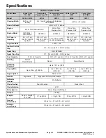
Страница 12: ...gnition Coil Air Gap 0 3 0 5 mm 0 011 0 019 inches Spark Plug NGK BPR6ES Spark Plug Gap 0 7 0 8 mm 0 028 0 032 inches Fuel Capacity 2 16 L 2 3 quarts 2 93 L 3 1 quarts 2 16 L 2 3 quarts 2 93 L 3 1 quarts Starting Recoil Recoil Electric Recoil Recoil Electric Throwing Distance Up to 10 7 m 35 ft Capcity Min Up to 816 kg 1800 lb Up to 861 8 kg 1900 lb Up to 816 kg 1800 lb Up to 861 8 kg 1900 lb Auge...

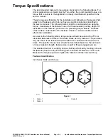
Страница 13: ...stener s head or similar condition which affects the installation As noted in the following tables torque values should be reduced by 25 for lubricated fasteners to achieve the similar stress as a dry fastener Torque values may also have to be reduced when the fastener is threaded into aluminum or brass The specific torque value should be determined based on the aluminum or brass material strength...

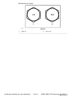
Страница 14: ...Metric Bolts and Screws g272209 Figure 2 1 Class 8 8 2 Class 10 9 Specifications and Maintenance Torque Specifications Page 2 4 POWER CLEAR 721 821 Snowthrower Service Manual 3438 776 Rev A ...

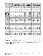
Страница 15: ...7 95 9 7 16 20 UNF 29 3 29 3 39 4 55 6 75 8 77 8 104 11 1 2 13 UNC 30 3 48 7 65 9 75 8 102 11 105 11 142 15 1 2 20 UNF 32 4 53 7 72 9 85 9 115 12 120 12 163 16 5 8 11 UNC 65 10 88 12 119 16 150 15 203 20 210 21 285 28 5 8 18 UNF 75 10 95 15 129 20 170 18 230 24 240 24 325 33 3 4 10 UNC 93 12 140 20 190 27 265 27 359 37 375 38 508 52 3 4 16 UNF 115 15 165 25 224 34 300 30 407 41 420 43 569 58 7 8 9...

Страница 16: ...alues listed in the table above by 25 for lubricated fasteners Lubricated fasteners are defined as threads coated with a lubricant such as oil graphite or thread sealant such as Loctite Torque values may have to be reduced when installing fasteners into threaded aluminum or brass The specific torque value should be determined based on the fastener size the aluminum or base material strength length...

Страница 17: ...UNC 38 7 in lb 1 4 20 UNC 85 15 in lb 5 16 18 UNC 110 20 in lb 3 8 16 UNC 200 100 in lb Hole size material strength material thickness and finish must be considered when determining specific torque values All torque values are based on non lubricated fasteners Conversion Factors in lb X 11 2985 N cm ft lb X 1 3558 N m N cm X 0 08851 in lb N cm X 0 73776 ft lb Thread Cutting Screws Zinc Plated Stee...

Страница 18: ...4375 18 653 1 4 0 2500 6 350 3 4 0 7500 19 050 17 64 0 265625 6 747 49 64 0 765625 19 447 9 32 0 28125 7 144 25 32 0 78125 19 844 19 64 0 296875 7 541 51 64 0 796875 20 241 5 16 0 3125 7 541 13 16 0 8125 20 638 21 64 0 328125 8 334 53 64 0 828125 21 034 11 32 0 34375 8 731 27 32 0 84375 21 431 23 64 0 359375 9 128 55 64 0 859375 21 828 3 8 0 3750 9 525 7 8 0 8750 22 225 25 64 0 390625 9 922 57 64 ...

Страница 19: ...et Cubic Meters 0 02832 Volume Cubic Inches Cubic Centimeters 16 39 Tons Short Metric Tons 0 9078 Pounds Kilograms 0 4536 Weight Ounces Grams 28 3495 Pressure Pounds Square Inch Kilopascal 6 895 Foot Pounds Newton Meters 1 356 Foot Pounds Kilogram Meters 0 1383 Work Inch Pounds Kilogram Centimeters 1 152144 Quarts Liters 0 9463 Liquid Volume Gallons Liters 3 785 Liquid Flows Gallons Minute Liters ...

Страница 20: ...Specifications and Maintenance Torque Specifications Page 2 10 POWER CLEAR 721 821 Snowthrower Service Manual 3438 776 Rev A ...

Страница 21: ...Chapter 3 Troubleshooting Table of Contents General Troubleshooting 3 3 POWER CLEAR 721 821 Snowthrower Service Manual Page 3 1 Troubleshooting 3438 776 Rev A ...

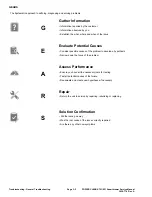
Страница 22: ...down the focus of the problem Assess Performance Ensure you have all the necessary tools for testing Test all potential causes of the failure A Reevaluate and create new hypotheses if necessary Repair R Return the unit to service by repairing rebuilding or replacing Solution Confirmation Did the issue go away Was the root cause of the issue correctly repaired S Are there any other new symptoms Tro...

Страница 23: ...General Troubleshooting See Operator s Manual for troubleshooting information POWER CLEAR 721 821 Snowthrower Service Manual Page 3 3 Troubleshooting General Troubleshooting 3438 776 Rev A ...

Страница 24: ...Troubleshooting General Troubleshooting Page 3 4 POWER CLEAR 721 821 Snowthrower Service Manual 3438 776 Rev A ...

Страница 25: ...ation 4 2 Service and Repairs 4 3 Engine Replacement 4 4 Electric Starter Replacement 4 9 Muffler Guard Replacement 4 12 Muffler Replacement 4 15 Fuel Tank Replacement 4 17 POWER CLEAR 721 821 Snowthrower Service Manual Page 4 1 Engine 3438 776 Rev A ...

Страница 26: ...ation The POWER CLEAR 721 models utilize the Toro G210 engine while the POWER CLEAR 821 utilizes the Toro G250 engine Engine General Information Page 4 2 POWER CLEAR 721 821 Snowthrower Service Manual 3438 776 Rev A ...

Страница 27: ...e and Repairs Engine Assembly g321046 Figure 3 1 Engine 3 Engine Side Support 2 Engine Plate 4 Engine Support POWER CLEAR 721 821 Snowthrower Service Manual Page 4 3 Engine Service and Repairs 3438 776 Rev A ...

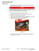
Страница 28: ...ntainer 3 Remove the shroud from the machine Shroud Removal page 5 8 4 Remove the recoil handle from the rope guide 5 Remove the 3 1 4 20 x 5 8 inch screws securing the belt cover to the auger housing Remove the belt cover from the auger housing 6 Unhook the extension spring from the idler arm g324732 Figure 4 7 Remove the 1 4 20 x 7 8 inch screw and Belleville washer securing the rotor pulley to ...

Страница 29: ... 1 1 4 inch screw and Belleville washer securing the engine pulley to the engine shaft Remove the engine pulley from the engine shaft g321398 Figure 6 11 Remove the 4 M8 x 1 25 mm x 5 8 inch bolts securing the engine to the engine plate Note Bolts are located inside the belt housing POWER CLEAR 721 821 Snowthrower Service Manual Page 4 5 Engine Service and Repairs 3438 776 Rev A ...

Страница 30: ...uts securing the engine support to the engine Note Do not flip the machine to replace the screws and nuts g321401 Figure 8 13 Using an appropriate lifting device remove the engine from the machine Engine Service and Repairs Page 4 6 POWER CLEAR 721 821 Snowthrower Service Manual 3438 776 Rev A ...

Страница 31: ...tall the engine onto the machine 2 Install the 2 5 16 18 x 1 3 8 inch screws and 2 nuts securing the engine support to the engine Note Do not flip the machine to remove the screws and nuts g321401 Figure 10 POWER CLEAR 721 821 Snowthrower Service Manual Page 4 7 Engine Service and Repairs 3438 776 Rev A ...

Страница 32: ...e 5 16 24 x 1 1 4 inch screw Install the screw and Belleville washer securing the engine pulley to the engine shaft Torque the screw 25 4 2 8 N m 225 25 in lb g321398 Figure 12 5 Route the belt first around the engine pulley under the flat idler pulley and finally around the loose rotor pulley positioned above the rotor shaft Engine Service and Repairs Page 4 8 POWER CLEAR 721 821 Snowthrower Serv...

Страница 33: ...m g324732 Figure 14 8 Install the belt cover to the auger housing Install the 3 1 4 20 x 5 8 inch screws securing the belt cover to the auger housing Torque the screws to 4 5 6 8 N m 40 60 in lb 9 Install the recoil handle to the rope guide 10 Install the shroud onto the machine Shroud Installation page 5 10 11 Refill the fuel and oil Electric Starter Replacement Electric Starter Removal 1 Remove ...

Страница 34: ... g323979 Figure 15 4 Remove the 2 M6 x 35 mm bolts securing the electric starter to the engine Note If the dowel pins were inadvertently removed retain for installation g323978 Figure 16 5 Remove the electric starter from the engine Electric Starter Installation 1 If the dowels were inadvertently removed install the dowel pins Engine Service and Repairs Page 4 10 POWER CLEAR 721 821 Snowthrower Se...

Страница 35: ...r to the engine Torque the bolts to 10 N m 89 in lb g323978 Figure 17 3 Wrap the harness clip around the electric starter wire g323979 Figure 18 4 Install the 2 6 x 2 5 in screws securing the electric starter switch box to the shroud Torque the screws to 6 78 N m 60 in lb 5 Install the engine onto the machine Engine Installation page 4 7 POWER CLEAR 721 821 Snowthrower Service Manual Page 4 11 Eng...

Страница 36: ... key 2 Remove the 2 1 4 10 x 13 16 inch screws securing the LH shroud retainer to the LH shroud Remove the LH shroud retainer from the LH shroud g320930 Figure 19 3 Remove the 6 M6 x 12 mm bolts securing the muffler guard to the engine g323692 Figure 20 Engine Service and Repairs Page 4 12 POWER CLEAR 721 821 Snowthrower Service Manual 3438 776 Rev A ...

Страница 37: ...uffler guard from the engine g323980 Figure 22 Muffler Guard Installation 1 Slide the lip of the muffler guard under the lip of the fuel tank 2 Install the 6 M6 x 12 mm bolts securing the muffler guard to the engine Torque the bolts to 8 47 N m 75 in lb POWER CLEAR 721 821 Snowthrower Service Manual Page 4 13 Engine Service and Repairs 3438 776 Rev A ...

Страница 38: ...inued g323692 Figure 23 g322776 Figure 24 3 Install the 2 1 4 10 x 13 16 inch screws securing the LH shroud retainer to the LH shroud Engine Service and Repairs Page 4 14 POWER CLEAR 721 821 Snowthrower Service Manual 3438 776 Rev A ...

Страница 39: ...the muffler guard from the engine Muffler Guard Removal page 4 12 2 Remove the 2 nuts securing muffler assembly to cylinder head g322787 Figure 26 3 Remove the muffler assembly and gasket from the engine POWER CLEAR 721 821 Snowthrower Service Manual Page 4 15 Engine Service and Repairs 3438 776 Rev A ...

Страница 40: ...hake the muffler to check if the internal baffle is loose Replace muffler if damaged Muffler Installation 1 Install the new gasket onto the exhaust studs Note Refer to figure for correct gasket orientation g322786 Figure 28 Engine Service and Repairs Page 4 16 POWER CLEAR 721 821 Snowthrower Service Manual 3438 776 Rev A ...

Страница 41: ...stop and remove the key 2 Drain the fuel from the fuel tank into a suitable container DANGER Fuel is very flammable and explosive under some conditions Do not smoke or let flames or sparks in your work area 3 Remove the shroud from the machine Shroud Removal page 5 8 4 Engines equipped with an electric starter only unwind the harness retainer clip and remove the electric start wire from the harnes...

Страница 42: ...has 3 M6 x 20 mm bolts and the G250 engine has 4 M6 x 20 mm bolts Refer to the Specifications chapter to find the engine model Specifications page 2 2 g323982 Figure 31 6 Remove the M6 x 20 mm fuel tank bolt securing the fuel tank to the engine Engine Service and Repairs Page 4 18 POWER CLEAR 721 821 Snowthrower Service Manual 3438 776 Rev A ...

Страница 43: ...fuel tank for rust corrosion or leaking on the inside and outside of the fuel tank Replace the fuel tank if damaged 2 Inspect the fuel filter for contamination blockage or if compromised Replace the fuel filter if damaged Fuel Tank Installation 1 Ensure the inside of the fuel tank tank outlet fitting and fuel filter fittings are all clean Install the fuel filter to the tank outlet 2 Connect the fu...

Страница 44: ...e fuel tank to the engine Torque the bolt to 8 47 N m 75 in lb g322779 Figure 35 4 Install the M6 x 20 mm bolts securing the front of the fuel tank to the engine The G210 engine has 3 M6 x 20 mm bolts and the G250 engine has 4 M6 x 20 mm bolts Refer to the Specifications chapter to find the engine model Engine Service and Repairs Page 4 20 POWER CLEAR 721 821 Snowthrower Service Manual 3438 776 Re...

Страница 45: ...y flammable and explosive under some conditions Do not smoke or let flames or sparks in your work area 7 Refill the fuel Fuel Tank Test DANGER Fuel is very flammable and explosive under some conditions Do not smoke or let flames or sparks in your work area 1 Add fuel to the fuel tank and verify no leaks exist Replace the fuel tank if leaking exists POWER CLEAR 721 821 Snowthrower Service Manual Pa...

Страница 46: ...Engine Service and Repairs Page 4 22 POWER CLEAR 721 821 Snowthrower Service Manual 3438 776 Rev A ...


Страница 47: ...hassis Table of Contents General Information 5 2 Service and Repairs 5 3 Shroud Replacement 5 8 Quick Shoot Controls Replacement 5 12 POWER CLEAR 721 821 Snowthrower Service Manual Page 5 1 Chassis 3438 776 Rev A ...

Страница 48: ...Information The chassis of both the 721 and 821 are the same size and use many of the same parts and fasteners Chassis General Information Page 5 2 POWER CLEAR 721 821 Snowthrower Service Manual 3438 776 Rev A ...

Страница 49: ...ute Handle 13 Pinion Sleeve Spacer 4 Side Cover 14 Gear Chute Ring 5 Deflector Ratchet Hinge 15 Pinion Bracket 6 Deflector Hinge Pin 16 Gear Pinion 7 Deflector Seal 17 Detent Pawl 8 Shroud Retainer 18 Cable Retainer 9 Shroud 19 Chute Support Ring 10 Chute 20 Lock Nut POWER CLEAR 721 821 Snowthrower Service Manual Page 5 3 Chassis Service and Repairs 3438 776 Rev A ...

Страница 50: ...de 2 Control Bail 8 Switch Box Support 3 Clutch Extension Spring 9 Box Support 4 Upper Handle 10 Support Cap 5 Clutch Cable Adjuster 11 Lower Handle 6 Handle Lock Chassis Service and Repairs Page 5 4 POWER CLEAR 721 821 Snowthrower Service Manual 3438 776 Rev A ...

Страница 51: ...er Pulley 9 Plate Chute Lock 3 Slider Handle RH 10 Cable Clamp 4 Short Chute Cable 11 Trigger 5 Handle Screw 12 Slider Handle LH 6 Long Chute Cable 13 Cable Bracket 7 Slider Track POWER CLEAR 721 821 Snowthrower Service Manual Page 5 5 Chassis Service and Repairs 3438 776 Rev A ...

Страница 52: ...Quick Shoot Controls 1 g321048 Figure 40 Chassis Service and Repairs Page 5 6 POWER CLEAR 721 821 Snowthrower Service Manual 3438 776 Rev A ...
Страница 53: ...Quick Shoot Controls 2 g321049 Figure 41 POWER CLEAR 721 821 Snowthrower Service Manual Page 5 7 Chassis Service and Repairs 3438 776 Rev A ...

Страница 54: ...x 1 5 inch plastite screw Note Some models will have a chute handle attached to the chute g321389 Figure 42 3 Remove the M4 2 2 25 mm x 3 4 inch screw securing the chute seal ring to the shroud Remove the chute seal ring from the shroud g320929 Figure 43 4 Remove the 2 1 4 10 x 13 16 inch screws securing the LH shroud retainer to the LH shroud Repeat the procedure on the RH side of the machine Cha...

Страница 55: ... inch screws securing the RH shroud to the side cover g320931 Figure 45 7 Remove the 2 6 x 2 5 inch screws and 2 hex nuts securing the shroud to the switch box Remove the shroud from the machine Note Remove the starter plug from the shroud if equipped with electric start POWER CLEAR 721 821 Snowthrower Service Manual Page 5 9 Chassis Service and Repairs 3438 776 Rev A ...

Страница 56: ... and 2 hex nuts securing the shroud to the switch box Note Install the starter plug to the shroud if equipped with electric start g320932 Figure 47 2 Install the 3 M4 2 x 2 25mm x 3 4 inch screws securing the RH shroud to the side cover Chassis Service and Repairs Page 5 10 POWER CLEAR 721 821 Snowthrower Service Manual 3438 776 Rev A ...

Страница 57: ...4 10 x 13 16 inch screws securing the LH shroud retainer to the LH shroud Remove the LH shroud retainer Repeat the procedure on the RH side of the machine g320930 Figure 49 5 Install the chute seal ring to the shroud secure with a screw M4 2 2 25 mm x 3 4 inch POWER CLEAR 721 821 Snowthrower Service Manual Page 5 11 Chassis Service and Repairs 3438 776 Rev A ...

Страница 58: ...ed to the chute g321389 Figure 51 Quick Shoot Controls Replacement Quick Shoot Controls Removal 1 Park the machine on a level surface Stop the engine wait for all moving parts to stop and remove the key 2 Remove the shroud from the machine Shroud Removal page 5 8 3 Remove the 1 4 20 x 2 25 inch screw and lock nut securing the chute ring retainer and quick chute gear assembly to the chute support r...

Страница 59: ...inion spacer sleeve from the quick chute gear assembly g320934 Figure 53 5 Using pliers compress the cable locks and remove the black and gray cables from the pinion bracket POWER CLEAR 721 821 Snowthrower Service Manual Page 5 13 Chassis Service and Repairs 3438 776 Rev A ...

Страница 60: ...mbly over so that the cable retainer is facing upwards Remove the cable retainer from the pinion gear Note With the cable retainer removed note the orientation of the cable g320936 Figure 55 Chassis Service and Repairs Page 5 14 POWER CLEAR 721 821 Snowthrower Service Manual 3438 776 Rev A ...

Страница 61: ... the pinion gear facing upwards route the black cable into the bottommost gear slot Insert the barrel end of the black cable into the slot and secure the cable under the gear tab g320938 Figure 57 2 Wrap the black cable around the bottom of the spool POWER CLEAR 721 821 Snowthrower Service Manual Page 5 15 Chassis Service and Repairs 3438 776 Rev A ...

Страница 62: ... g320939 Figure 58 g320940 Figure 59 3 Insert the barrel end of the gray cable into the slot in the gear and secure the cable under the gear tab Chassis Service and Repairs Page 5 16 POWER CLEAR 721 821 Snowthrower Service Manual 3438 776 Rev A ...
Страница 63: ...ntrols Installation continued g320941 Figure 60 4 Wrap the gray cable around the top of the spool g320942 Figure 61 POWER CLEAR 721 821 Snowthrower Service Manual Page 5 17 Chassis Service and Repairs 3438 776 Rev A ...

Страница 64: ... 5 Slide the pinion gear into the pinion bracket and secure the cable locks g320935 Figure 63 6 Insert the pinion spacer sleeve into the quick chute gear assembly Chassis Service and Repairs Page 5 18 POWER CLEAR 721 821 Snowthrower Service Manual 3438 776 Rev A ...
Страница 65: ... gear retainer and chute support ring Install the 1 4 20 x 2 25 inch screw and lock nut securing the chute ring retainer and quick chute gear assembly to the chute support ring Note Do not over tighten g320944 Figure 65 POWER CLEAR 721 821 Snowthrower Service Manual Page 5 19 Chassis Service and Repairs 3438 776 Rev A ...

Страница 66: ...ntrols Installation continued g320933 Figure 66 8 Install the shroud onto the machine Shroud Installation page 5 10 Chassis Service and Repairs Page 5 20 POWER CLEAR 721 821 Snowthrower Service Manual 3438 776 Rev A ...
Страница 67: ... Contents General Information 6 2 Service and Repairs 6 3 Belt Replacement 6 6 Rotor Replacement 6 7 Paddle Replacement 6 11 Scraper Replacement 6 13 POWER CLEAR 721 821 Snowthrower Service Manual Page 6 1 Drive System 3438 776 Rev A ...

Страница 68: ...neral Information All POWER CLEAR 721 and 821 models utilize Toro s Power Propel self propel system Drive System General Information Page 6 2 POWER CLEAR 721 821 Snowthrower Service Manual 3438 776 Rev A ...
Страница 69: ... 1 Cable Clutch 6 Flat Idler Pulley 2 Engine Pulley 7 Spring Clip 3 Belleville Washer 8 Pivot Pushing 4 Extension Spring 9 Rotor Pulley 5 Idler Arm 10 Belt POWER CLEAR 721 821 Snowthrower Service Manual Page 6 3 Drive System Service and Repairs 3438 776 Rev A ...

Страница 70: ...otor Assembly g320854 Figure 68 1 Rotor Blade 4 Rotor Blade Spacer 2 Lock Nut 5 Rotor 3 Rotor Half Drive System Service and Repairs Page 6 4 POWER CLEAR 721 821 Snowthrower Service Manual 3438 776 Rev A ...
Страница 71: ...ring Spacer 2 Auger Housing 8 Rubber Washer 3 Belt Cover 9 Shoulder Bolt 4 Bearing Flange 10 Lower Chute 5 Thrust Washer 11 Scraper Blade 6 Ball Bearing POWER CLEAR 721 821 Snowthrower Service Manual Page 6 5 Drive System Service and Repairs 3438 776 Rev A ...

Страница 72: ...tor shaft 5 Remove the belt from the engine pulley and rotor pulley Belt Installation 1 Route the belt first around the engine pulley under the flat idler pulley and finally around the loose rotor pulley positioned above the rotor shaft 2 Install the rotor pulley onto the rotor shaft Apply blue threadlocker to threads of the new 1 4 20 x 7 8 inch screw Install the Belleville washer and screw secur...

Страница 73: ...using Torque the screws to 4 5 6 8 N m 40 60 in lb Rotor Replacement Rotor Removal 1 Park the machine on a level surface Stop the engine wait for all moving parts to stop and remove the key 2 Remove the belt Belt Removal page 6 6 3 Remove the 3 1 4 20 x 1 2 inch rotor bearing screws securing the LH sideplate to the rotor assembly POWER CLEAR 721 821 Snowthrower Service Manual Page 6 7 Drive System...

Страница 74: ... 1 4 20 x 1 inch rotor bearing screws securing the RH sideplate to the rotor assembly g320946 Figure 75 5 Remove the rotor assembly from the auger housing Drive System Service and Repairs Page 6 8 POWER CLEAR 721 821 Snowthrower Service Manual 3438 776 Rev A ...

Страница 75: ...r parts as necessary g321788 Figure 77 1 Screw 4 Ball Bearing 2 RH Bearing Spacer 5 Thrust Washer 3 Rubber Washer 6 Bearing Flange Rotor Installation 1 Install the bearing flange thrust washer ball bearing and rubber washer onto the rotor assembly Install the 3 8 16 x 3 4 inch screw securing the RH bearing spacer to the RH end cap POWER CLEAR 721 821 Snowthrower Service Manual Page 6 9 Drive Syste...

Страница 76: ...tor assembly into the auger housing Install the 3 1 4 20 x 1 inch rotor bearing screws securing the RH sideplate to the rotor assembly g320946 Figure 79 3 Install the 3 1 4 20 x 1 2 inch rotor bearing screws securing LH sideplate to the rotor assembly Drive System Service and Repairs Page 6 10 POWER CLEAR 721 821 Snowthrower Service Manual 3438 776 Rev A ...

Страница 77: ...oving parts to stop and remove the key 2 Remove the 4 1 4 20 x 3 4 inch Torx head screws securing the paddles together g321393 Figure 81 3 Remove the 4 1 4 20 x 1 1 2 inch screws 4 spacers and 4 lock nuts securing the paddles to the 2 paddle spacers Remove the paddles from the rotor assembly POWER CLEAR 721 821 Snowthrower Service Manual Page 6 11 Drive System Service and Repairs 3438 776 Rev A ...

Страница 78: ...he thicker rubber layer is assembled to the forward facing side of the rotor assembly Install the 4 1 4 20 x 1 1 2 inch screws 4 spacers and 4 washers securing the paddles to the 2 paddle spacers g327312 Figure 83 Drive System Service and Repairs Page 6 12 POWER CLEAR 721 821 Snowthrower Service Manual 3438 776 Rev A ...
Страница 79: ...lacement Scraper Removal 1 Park the machine on a level surface Stop the engine wait for all moving parts to stop and remove the key 2 Flip the machine over so the auger housing is facing the floor Remove the springs from the LH and RH sides of the scraper POWER CLEAR 721 821 Snowthrower Service Manual Page 6 13 Drive System Service and Repairs 3438 776 Rev A ...

Страница 80: ...he auger housing g321396 Figure 87 Scraper Installation 1 Flip the machine over so the auger housing is facing the floor Install the scraper onto handle auger housing Install the 2 3 8 16 x 2 1 2 inch shoulder bolts securing the scraper to the auger housing Drive System Service and Repairs Page 6 14 POWER CLEAR 721 821 Snowthrower Service Manual 3438 776 Rev A ...
Страница 81: ...H and RH sides of the scraper Install the lower hooks of the spring so that the open end of the hooks are installed through the front holes of the scraper blade g321395 Figure 89 POWER CLEAR 721 821 Snowthrower Service Manual Page 6 15 Drive System Service and Repairs 3438 776 Rev A ...

Отзывы: