background image

Important:

Ensure that the curved side of the

cable clamp is against the handle and that the
cable is routed below the clamp bolt. The cable
must be in a straight line from the cable clamp
to the point where it attaches to the wheel clutch
lever.

4. Pull the cable jacket down gently until the wheel

clutch lever is down and the slack is out of the cable,
then tighten the cable clamp nut securely (Figure 8).

Figure 8

5. Squeeze the lever fully, then check the gap between

the bottom of the handle and the wheel clutch lever
end (Figure 9).

Figure 9

Note:

The gap should be approximately the

thickness of a pencil (1/4 inch or 6 mm). If it is
greater, loosen the cable clamp nut, slide the cable
jacket up slightly, tighten the cable clamp nut, and
check the gap again.

6. Repeat steps 2 through 5 for the other cable.

3. Installing the Traction
Control Linkage

Procedure

1. Remove the hairpin cotter and washer from the

lower end of the speed control rod and insert the
lower end of the rod into the lower link arm so that
the bent end of the speed control rod faces rearward
(Figure 10).

Figure 10

2. Secure the lower end of the speed control rod with

the washer and hairpin cotter that you previously
removed.

3. Remove the hairpin cotter and the outer washer

from the trunnion on the upper end of the speed
control rod (Figure 11).

Figure 11

1.

Speed selector lever

3.

Inner washer

2.

Trunnion

4.

Outer washer

Note:

To make installation easier, leave the flat

washer on the trunnion (Figure 11).

4. Shift the speed selector lever into Position R2.

5. Rotate the lower link arm fully upward

(counterclockwise) (Figure 12).

Figure 12

8

Содержание 38637

Страница 1: ...gure 1 identifies the location of the model and serial numbers on the product Write the numbers in the space provided Figure 1 1 Model and serial number location Model No Serial No This manual identifies potential hazards and has safety messages identified by the safety alert symbol Figure 2 which signals a hazard that may cause serious injury or death if you do not follow the recommended precauti...

Страница 2: ...ontrols quickly Never allow children to operate the equipment Never allow adults to operate the equipment without proper instruction Keep the area of operation clear of all persons particularly small children and pets Exercise caution to avoid slipping or falling especially when operating in reverse Preparation Thoroughly inspect the area where the equipment is to be used and remove all doormats s...

Страница 3: ...ect discharge at bystanders or allow anyone in front of the unit Disengage power to the collector impeller when snow thrower is transported or not in use Use only attachments and accessories approved by the manufacturer of snow thrower such as wheel weights counterweights cabs etc Never operate the snow thrower without good visibility or light Always be sure of your footing and keep a firm hold on...

Страница 4: ...in the fuel from the fuel tank to prevent a potential hazard Store fuel in an approved fuel container Remove the key from the ignition switch before storing the snowthrower Purchase only genuine Toro replacement parts and accessories Sound Pressure This unit has a maximum sound pressure level at the operator s ear of 86 dBA based on measurements of identical machines per EN 11201 Sound Power This ...

Страница 5: ...Auger impeller drive squeeze the lever to engage release the lever to disengage 2 Traction drive squeeze the lever to engage release the lever to disengage 4 Cutting dismemberment hazard impeller do not place your hand in the chute stop the engine before leaving the operator s position use the tool to clear the chute 6 Thrown object hazard keep bystanders a safe distance from the snowthrower 8 Rig...

Страница 6: ...to verify that all parts have been shipped Procedure Description Qty Use Handle bolts 4 Curved washers 4 1 Locknuts 4 Install the upper handle 2 No parts required Install the wheel clutch cable ends 3 No parts required Install the traction control linkage Carriage bolts 2 4 Locknuts 2 Install the chute control rod 5 Cable tie 1 Connect the wire to the headlight 6 No parts required Fill the engine ...

Страница 7: ...e sections Figure 3 1 Cables 2 Secure the upper handle with 4 handle bolts 4 curved washers and 4 locknuts from the loose parts bag Figure 4 Figure 4 2 Installing the Wheel Clutch Cable Ends Procedure 1 Unwrap the cable ends from the lower handle Figure 5 Figure 5 2 Route either the left or right cable end over the lower handle and insert the cable end into the hole in the corresponding wheel clut...

Страница 8: ...htly tighten the cable clamp nut and check the gap again 6 Repeat steps 2 through 5 for the other cable 3 Installing the Traction Control Linkage Procedure 1 Remove the hairpin cotter and washer from the lower end of the speed control rod and insert the lower end of the rod into the lower link arm so that the bent end of the speed control rod faces rearward Figure 10 Figure 10 2 Secure the lower e...

Страница 9: ...er fully rearward Note The discharge chute and deflector should face forward If they do not hold the blue trigger cap down but do not move the Quick Stick and rotate the discharge chute until they do 3 Align the flattened back end of the long chute control rod with the flattened front end of the short rod that extends from the control panel so that they nest together Figure 14 Figure 14 1 Short ro...

Страница 10: ...Filling the Engine with Oil Procedure Your snowthrower comes with 20 oz of oil in the engine crankcase Note Before starting the engine check the oil level and add oil if necessary Max fill 20 oz 0 55 l type automotive detergent oil with an API service classification of SF SG SH SJ SL or higher Use SAE 5W30 or SAE 10W30 oil Refer to your engine owner s manual 1 Remove the dipstick and slowly pour o...

Страница 11: ...r Figure 11 C Turn the trunnion downward clockwise on the speed control rod Figure 11 D Connect the trunnion to the speed selector lever Figure 11 4 Release the traction lever 5 Move the speed selector to the Position 1 refer to Operating the Speed Selector 6 Squeeze the left hand traction lever to the hand grip Figure 19 The snowthrower should move forward If the snowthrower does not move or move...

Страница 12: ...hine from the normal operating position Filling the Fuel Tank Gasoline is extremely flammable and explosive A fire or explosion from gasoline can burn you and others To prevent a static charge from igniting the gasoline place the container and or snowthrower on the ground before filling not in a vehicle or on an object Fill the tank outdoors when the engine is cold Wipe up spills Do not handle gas...

Страница 13: ...ve 1 4 turn counterclockwise to open it Figure 24 Figure 24 3 Insert the ignition key Figure 25 Figure 25 1 Ignition key 4 Firmly push in the primer with your thumb 2 times 15 F or 9 C or above or 4 times below 15 F or 9 C holding the primer in for a second before releasing it each time Figure 26 Figure 26 5 Rotate the choke to the Choke position Figure 27 13 ...

Страница 14: ...zed Service Dealer for service 8 Disconnect the power cord from the power outlet first and then from the snowthrower electric start only 9 Allow the engine to warm up for several minutes move the choke toward the Run position Wait for the engine to run smoothly before each choke adjustment If you leave the snowthrower plugged into a power outlet someone can inadvertently start the snowthrower and ...

Страница 15: ...Freewheeling or Using the Self propel Drive 1 To engage the traction drive squeeze the left hand traction lever to the handgrip Figure 32 Figure 32 2 To stop the traction drive release the traction lever Using the Wheel Clutch Levers The wheel clutch levers allow you to momentarily disengage the drive to one or both wheels with the traction drive lever still engaged This enables you to turn and ma...

Страница 16: ... both the auger impeller lever and the traction lever the traction lever locks the auger impeller lever down freeing your right hand To release both levers simply release the left hand traction lever 3 If the auger and impeller continue to rotate when you release the auger impeller lever do not operate the snowthrower Check the auger impeller cable refer to Checking and Adjusting the Auger Impelle...

Страница 17: ...r on the pavement Repeat if necessary until a stream of snow comes out the discharge chute If you cannot unclog the discharge chute by bumping the front of the snowthrower stop the engine wait for all moving parts to stop and use the snow cleanout tool never use your hand Important Unclogging the discharge chute by bumping the front of the snowthrower on the pavement may cause the skids to move Ad...

Страница 18: ... behind the handles and away from the discharge opening while operating the snowthrower Keep face hands feet and any other part of your body or clothing away from concealed moving or rotating parts The rotor blades can throw stones toys and other foreign objects and cause serious personal injury to the operator or to bystanders Keep the area to be cleared free of all objects that the rotor blades ...

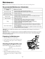
Страница 19: ...res and inflate them to 17 20 psi 116 137 kPa Drain the gasoline and run the engine to dry out the fuel tank and the carburetor at the end of the season Have an Authorized Service Dealer inspect and replace the traction drive belt and or the auger impeller drive belt if necessary Important You can find more information about maintaining and servicing your snowthrower at www Toro com Important Refe...

Страница 20: ...tighten the nuts that secure both skids to the auger sides Note To quickly adjust the skids if they loosen support the scraper 1 8 inch 3 mm off the pavement then adjust the skids down to the pavement Note If the skids become excessively worn you can turn them over and set the unused side toward the pavement Checking and Adjusting the Traction Cable Service Interval After the first 2 hours Inspect...

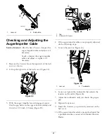
Страница 21: ...r disengaged ensure that the gap between the auger clutch assembly and the tab is 1 16 inch 1 5 mm Figure 45 Figure 45 1 Tab 2 1 16 inch 1 5 mm 4 If the auger impeller cable is not properly adjusted do the following steps 5 Loosen the jam nut Figure 46 Figure 46 1 Jam nut 2 Turnbuckle 6 Loosen or tighten the turnbuckle that adjusts the tension on the cable Figure 46 7 Adjust the turnbuckle until y...

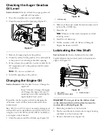
Страница 22: ...ies more contaminants Max fill 20 oz 0 55 l type automotive detergent oil with an API service classification of SF SG SH SJ SL or higher Use SAE 5W30 or SAE 10W30 oil Refer to your engine owner s manual 1 Clean the area around the oil drain cap Figure 48 Figure 48 1 Oil drain cap 2 Slide an oil drain pan under the drain extension and remove the oil drain cap 3 Drain the oil Note Dispose of the use...

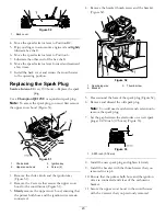
Страница 23: ...Remove the 2 screws that secure the upper snow hood to the snowthrower Figure 51 3 Slowly remove the upper snow hood ensuring that the primer bulb hose and the ignition wire remain connected 4 Remove the bracket thumb screw and the bracket Figure 52 Figure 52 1 Spark plug wire 3 Thumb screw 2 Bracket 5 Clean around the base of the spark plug Figure 52 6 Remove and discard the old spark plug Note Y...

Страница 24: ... the gear teeth Figure 55 and Figure 56 Figure 56 1 Discharge chute latch 2 Gear teeth Note The latch is spring loaded and will naturally move into the teeth of the gear Figure 56 4 Remove any slack in the cable by pulling the cable conduit rearward 5 Tighten the bolt on the cable clamp 6 Install and secure the gear cover Replacing the Drive Belts If the auger impeller drive belt or the traction d...

Страница 25: ... 59 Figure 59 4 Insert a new bulb into the back of the headlight Figure 60 Figure 60 5 Turn the base of the bulb clockwise until it is snug Figure 61 Figure 61 6 Insert the wire connector straight into the back of the headlight until it is securely in place Figure 62 Figure 62 25 ...

Страница 26: ...connect the spark plug wire 12 Remove the spark plug add 1 2 oz 15 ml of oil through the spark plug hole and pull the starter rope slowly several times to distribute oil throughout the cylinder to prevent cylinder corrosion during the off season 13 Loosely install the spark plug 14 Dispose of any unused fuel properly Recycle it according to local codes or use it in your automobile Note Do not stor...

Страница 27: ...ow or too high 9 Add or drain oil to adjust the oil level in the engine crankcase to the Full mark on the dipstick 1 The choke is in the On position 1 Move the choke to the Off position 2 The fuel shutoff valve is not completely open 2 Open the fuel shutoff valve 3 The fuel tank is nearly empty or contains stale fuel 3 Drain and fill the fuel tank with fresh gasoline not more than 30 days old If t...

Страница 28: ...ed Service Dealer Discharge chute either does not lock into place or does not move 1 The discharge chute latch is not properly adjusted 1 Adjust the discharge chute latch 1 The skids and or scraper are not properly adjusted 1 Adjust the skids and or the scraper Snowthrower does not properly clear the snow off the surface 2 The pressure in the tires is not equal 2 Check and adjust the pressure in o...

Страница 29: ...Notes 29 ...

Страница 30: ...Notes 30 ...

Страница 31: ...LLC Egypt 202 519 4308 Ibea S p A Italy 39 0331 853611 Irriamc Portugal 351 21 238 8260 Jean Heybroek b v Netherlands 31 30 639 4611 Lely U K Limited United Kingdom 44 1480 226 800 Maquiver S A Colombia 57 1 236 4079 Maruyama Mfg Co Inc Japan 81 3 3252 2285 Metra Kft Hungary 36 1 326 3880 Mountfield a s Czech Republic 420 255 704 220 Munditol S A Argentina 54 11 4 821 9999 Oslinger Turf Equipment ...

Страница 32: ...f the product If for any reason it is impossible for you to contact your seller you may contact any Toro Authorized Distributor to arrange service 2 Bring the product and your proof of purchase sales receipt to your seller or the Service Dealer If for any reason you are dissatis ed with the Service Dealer s analysis or with the assistance provided contact the Toro importer or contact us at Custome...

Отзывы: