5
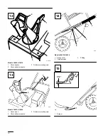
Install Discharge Chute And
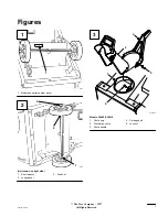
Chute Handle (Fig. 3)
Models 38409 & 38414
1.
Place chute handle over chute ring.
2.
Insert discharge chute between chute ring and
chute handle. Align holes.
3.
Secure back of chute and handle to center hole in
chute ring with a carriage bolt and lock nut.
Position nut on outside of chute.
Note:
Chute ring may be rotated to ease
assembly of discharge chute.
4.
Secure chute and handle to remaining holes in
chute ring and tighten all nuts SECURELY.
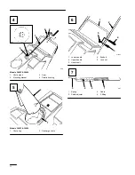
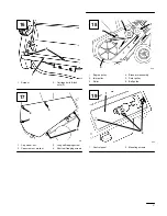
Install Chute Crank (Fig. 4)
Models 38422 & 38424
1.
Insert flattened end of chute crank through hole
in shroud while aligning mounting bracket with
holes in lower handle. Slowly rotate crank until
flattened end fits into hidden gear opening and
chute ring turns with crank. Make sure plastic
bushing is fully inserted into hole in mounting
bracket, then secure mounting bracket to handle
with (2) capscrews and locknuts.
Install Discharge Chute (Fig. 5)
Models 38422 & 38424
1.
Set discharge chute onto chute ring. Align hole
in back of chute with center hole in ring and
install a carriage bolt and sems locknut. Position
nut on outside of chute.
Note:
Chute ring may be rotated to ease
assembly of discharge chute.
2.
Secure chute to remaining holes in chute ring
and tighten all nuts SECURELY.
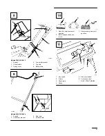
Install Handle (Fig. 6)
1.
Remove tie securing control cable to lower
handle.
2.
Position upper handle so that control bar is on
top of handle, not underneath it.
3.
Secure upper and lower handle in place with (3)
handle bolts, (1) eyebolt, and (4) lock nuts. Use
eyebolt to mount upper left side of handle.
Eyebolt must be positioned perpendicular to
handle when tightened.
Install Control Cable
Models 38409 & 38414
1.
Route control cable through eyebolt on left side
of snowthrower.
2.
Hook spring to round hole at end of cable
adjuster (Fig. 7).
3.
Route cable through elongated hole in cable
adjuster. Insert Z fitting on end of cable into 3rd
hole on cable adjuster (Fig. 7).
4.
Slide spring cover over spring and cable adjuster.
Push spring end through hole at end of spring
cover.
5.
Hook spring into top hole of control bar bracket
(Fig. 8).
6.
Move control bar back toward handle until slack
in cable is removed. The gap between the control
bar bracket and handle should be approximately
1/16”-1/8”. See insert, Figure 8. If an adjustment
is required, refer to Adjusting Control Bar,
page 9.
Note:
The control cable must always have
slack in it when in the disengaged
position.
Содержание 38409
Страница 8: ...vi 1 628 1 Spark plug wire 0 032 0 81 mm 110 1 1 Wear indicator hole 20 21 22 ...
Страница 27: ......


