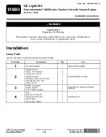
Toro 30660 Скачать руководство пользователя страница 9

g021710

2

1

1

3

4

5

Figure 15

1.

Jumper wire harness

4.

L.H. lamp mount

2.

R.H. lamp mount

5.

Rear lamp (2)

3.

Harness clip

3.

Mount the rear lamp to lamp mount with bolts and
nuts included with the lamp (Figure 15).

Note:

Make sure the lamp is positioned so the plug is

through the hole in the lamp mount and the amber end
is toward the outside of the machine.

4.

Repeat the procedure on the right side of the machine.

5.

Plug the enclosed rear light wire harness jumpers into
the harness connectors of the machines rear wire
harness.

6.

Route the right harness under the right side of the
traction unit to the right rear lamp. Plug the harness
connector into the lamps pig tail connector (Figure 15).

7.

Route the left harness under the left side of the traction
unit to the left rear lamp. Plug the harness connector
into the lamps pig tail connector (Figure 15).

8.

Secure the wiring harness and jumper wires the harness
clips and cable ties.

8

Installing the Fuses

Parts needed for this procedure:

3

Fuse, 10 amp

Procedure

Insert the 10 amp fuses into the fuse block slots shown in
Figure 16 and Figure 17.

g021712

1

Figure 16

1.

Fuses, 10 amp (3)

g02171 1

1

Figure 17

1.

Fuse locations on decal

9

Содержание 30660

Страница 1: ...tion Qty Use 1 No parts required Disconnect the battery Flasher mount 1 Screw 1 4 x 5 8 inch 2 Flange nut 1 4 inch 2 Flasher module 1 Machine screw 10 x 5 8 inch 1 Flat washer 216 x 500 2 2 Lock nut 1...

Страница 2: ...30608 1 Screw 1 2 x 1 inch 2 Locknut 1 2 inch 2 Headlamp R H 1 Headlamp L H 1 Wire harness headlight 1 5 Harness clip 2 Install the headlights 6 Switch light 1 Install the light switch L H light moun...

Страница 3: ...ts needed for this procedure 1 Flasher mount 2 Screw 1 4 x 5 8 inch 2 Flange nut 1 4 inch 1 Flasher module 1 Machine screw 10 x 5 8 inch 2 Flat washer 216 x 500 1 Lock nut 10 Procedure 1 Remove the st...

Страница 4: ...tch g021714 1 2 Figure 4 1 Hazard switch 2 Turn signal switch 3 Install the hazard switch into the upper right hole in the steering tower dash panel Figure 4 The hazard switch is a On None On switch a...

Страница 5: ...ring column tower Plug the wire harness connectors labeled horn into the horn and switch 5 Secure the wire harness Note When routing the wires ensure that the operation of the tilt steering does not d...

Страница 6: ...connector through the end of the appropriate harness bracket out the hole grommet and connect it to the headlight Figure 8 8 Secure the headlight wiring harness to the headlight brackets and operator...

Страница 7: ...H headlight assemblies to the headlight brackets Figure 11 with the fasteners supplied with the lights Make sure the turn signal lens on the headlight is positioned toward the outside of the machine...

Страница 8: ...r and plate to the right side of the control arm 7 Installing the Rear Lamps Parts needed for this procedure 1 L H light mount 1 R H light mount 2 Rear lamp assembly 2 Jumper wire harness 2 Harness cl...

Страница 9: ...of the machines rear wire harness 6 Route the right harness under the right side of the traction unit to the right rear lamp Plug the harness connector into the lamps pig tail connector Figure 15 7 R...

Страница 10: ...9 Connecting the Battery No Parts Required Procedure Connect the negative battery cable to the battery post 10...

Страница 11: ...enter position is off Press down on the right side of the turn signal switch Figure 19 to activate the right turn signal The center position is off Horn Press the horn button to activate the horn Figu...

Страница 12: ......

Отзывы: