


Maintenance Service
Interval
Maintenance Procedure
Every 500 hours
• Replace the secondary air cleaner element. (May need more often under severe
conditions. See the Engine Owner’s Manual for additional information.)
• Replace the paper air-cleaner element (more often under severe conditions).
Every 800 hours
• Replace the fuel filter.
Yearly
• Grease the front caster pivots.
• Grease the belt idler pivot.
• Grease the caster pivots and hubs.
• Lubricate the caster wheel hubs.
• Lubricate the caster wheel hubs.
• Check the torque of the wheel hub nuts.
• Check the torque on the wheel lug nuts.
• Check the torque of the transmission output shaft nut.
Yearly or before storage
• Touch up chipped paint
Premaintenance
Procedures
CAUTION
Raising the machine for service or maintenance
relying solely on mechanical or hydraulic jacks
could be dangerous. The mechanical or hydraulic
jacks may not be enough support or may
malfunction allowing the machine to fall, which
could cause injury.
Do not rely solely on mechanical or hydraulic jacks
for support. Use adequate jack stands or equivalent
support.
Preparing for the Machine for
Maintenance
Perform the following before servicing, cleaning, or making
any adjustments to the machine.
1.
Move the machine to a level surface.
2.
Turn the key in the ignition switch to the O
FF
position,
set the parking brake, wait for all moving parts to stop.
3.
Remove the key from the key switch.
Accessing the Console
Compartment
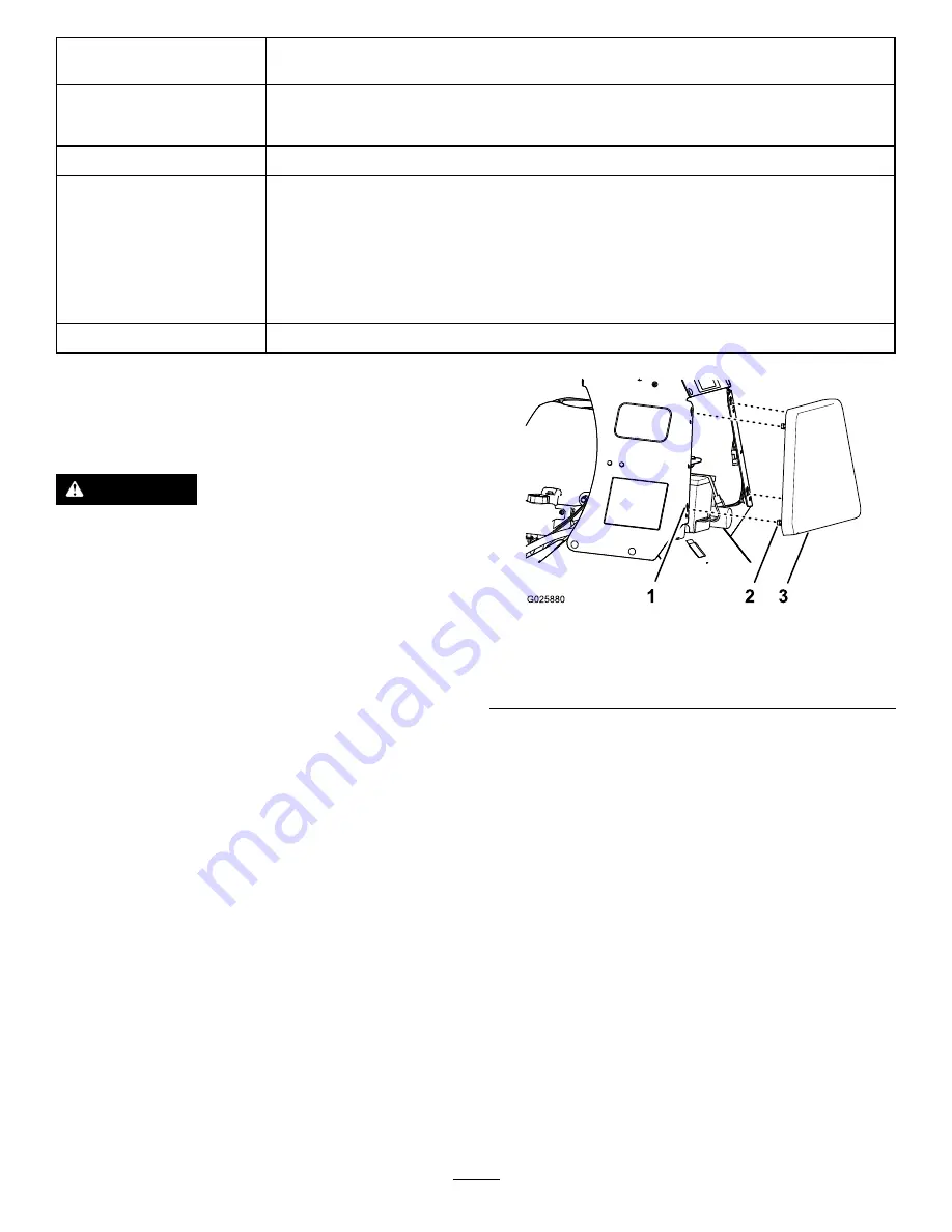
Removing the Console Pad
1.
Loosen the 4 flanged-head bolts that secure the pad to
the left and right console panels (
).
Figure 29
1.
Keyhole slot (console
panel)
3.
Pad
2.
Fanged-head bolt
2.
Lift up the console pad (
) approximately 13
mm (1/2 inch).
3.
Pull the console pad straight back and remove the pad
from the machine (
Installing the Console Pad
1.
Align the 4 flanged-head bolts at the forward face of
the console pad to the 4 keyhole slots in the frame of
the console (
2.
Move the pad forward until the pad is flush to the
console frame (
3.
Move the pad down until the flanged-head bolts are
seated in the keyhole slots (
4.
Torque the flanged-head bolts to 1978 to 2542 N-cm
(175 to 225lb-in).
28
Содержание 23518
Страница 53: ...Schematics Electrical Diagram Rev A 53...
Страница 54: ...Electrical Schematic Rev A 54...
Страница 55: ...Hydraulic Diagram Rev A 55...