18
Adjusting the Motion Control
Levers
The motion control levers can be adjusted higher or lower
for maximum operator comfort.
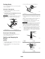
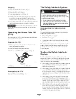
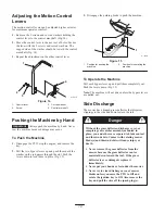
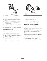
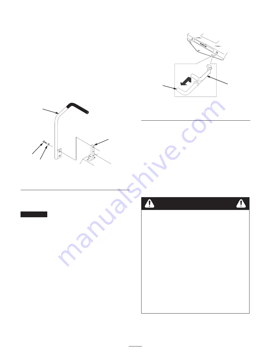
1. Remove the 2 screws and curved washers holding the
control lever to the control arm shaft (Fig. 14).
2. Move the control lever to the next set of holes. Secure
the lever with the 2 screws and curved washers. The
cupped side of the washer should be toward the control
arm shaft (Fig. 14).
3. Repeat the adjustment on the other control lever.
m–5215
1
2
3
4
Figure 14
1.
Control lever
2.
Screw
3.
Curved washer
4.
Control arm shaft
Pushing the Machine by Hand
Important
Always push the machine by hand. Never
tow the machine because damage may occur.
To Push the Machine
1. Disengage the PTO, stop the engine, and remove the
key.
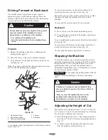
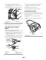
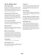
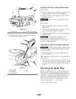
2. Pull the two bypass levers up and push them until the
washer on the rod passes through the slot. Push the
levers down to lock them in place (Fig. 15).
3. Disengage the parking brake to push the machine.
m–5139
1
2
Figure 15
1.
Position for pushing the
machine
2.
Position for operating the
machine
To Operate the Machine
Pull each bypass lever up and pull them completely out.
Push the levers down (Fig. 15).
Note: The machine will not drive unless the bypass levers
are pulled out.
Side Discharge
The mower has a hinged grass deflector that disperses
clippings to the side and down toward the turf.
Danger
Without the grass deflector, discharge cover, or
complete grass catcher assembly mounted in
place, you and others are exposed to blade contact
and thrown debris. Contact with rotating mower
blade(s) and thrown debris will cause injury or
death.
•
Never remove the grass deflector from the
mower because the grass deflector routes
material down toward the turf. If the grass
deflector is ever damaged, replace it
immediately.
•
Never put your hands or feet under the mower.
•
Never try to clear discharge area or mower
blades unless you move the PTO to Off and
rotate the ignition key to Off. Also remove the
key and pull the wire off the spark plug(s).

