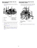
Figure 7
1.
Master spray valve
4.
Valve electrical connector
(agitation valve)
2.
Rate valve
5.
3-contact connector
(wire harness—
AGITATION
VALVE
)
3.
Agitation valve
6.
Valve electrical connector
(master spray valve)
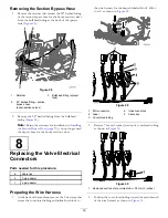
5.
Remove the 3-contact connector of the wire harness
from the valve (
).
6.
Repeat steps
and
for the 3-contact connectors of
the wire harness labeled
RATE VALVE
and
AGITATION
VALVE
.
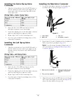
7.
Remove the 5 push-in fasteners of the wire
harness from the section-valve bracket and the
agitation/rate/master-spray bracket.
Figure 8
1.
Bracket (throttle valve)
3.
Bracket
(agitation/rate/master-spray
valve)
2.
Push-in fastener
8
Содержание 136-0372
Страница 61: ...Schematics Flow Diagram Rev A 61...
Страница 62: ...Notes...
Страница 63: ...Notes...
Страница 64: ......


