Installation Instructions
4
2
1 3
4
Figure 6
1.
Brake cable
2.
Brake arm
3.
Brake cable fitting
4.
Brake assembly
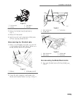
2. Use a pliers to squeeze the tabs on the top and the
bottom of the blade brake cable fitting, and slide the
cable out of the brake assembly (Fig. 6).
Self-propelled Models only
3. Cut the cable ties that secure the blade brake cable to
the right side of the handle.
4. Remove the cable support, the screw, and the nut from
the right side of the handle.
5. Remove the blade brake cable from the cable support.
6. Unhook the blade brake cable from the control bar
control lever.
7. Retain the cable support, the screw, and the nut for
installing the new cable.
Removing the Blade Assembly
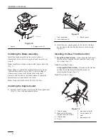
1. Remove the blade bolt, the lock washer, the blade
stiffener/accelerator, the blade, the blade retainer, the
spacer, and the square key, and the crankshaft
protector (Fig. 7).
1
2
3
4
5
6
7
8
9
10
11
Figure 7
1.
Blade bolt
2.
Lock washer
3.
Blade stiffener/accelerator
4.
Blade
5.
Blade retainer
6.
Spacer
7.
Square key
8.
Self-tapping screw (3)
9.
Internal lock washer (3)
10. Crankshaft protector
11. Engine drive pulley
(self-propelled models
only)
Note: Discard the old blade retainer, the spacer, and the
square key.
2. Remove the crankshaft protector by removing three
self-tapping screws and three internal lock washers.
Note: Keep all these items for the installation.
3. Remove and discard the engine drive pulley
(self-propelled models only).
Removing the Old Engine
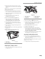
Remove the three engine screws and carefully lift the
engine off the housing (Fig. 8). Discard the screws and the
engine.

