background image

Maintenance

Note:

Determine the left and right sides of the

machine from the normal operating position.

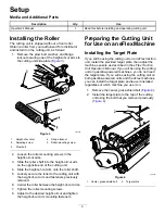
Supporting the Cutting Unit

Whenever you need to tip the cutting unit to expose
the bedknife/reel, prop up the rear of the cutting unit
to ensure that the nuts on the back end of the bedbar
adjusting screws are not resting on the work surface
(

Figure 8

).

g278461

Figure 8

1.

Prop (not provided)

2.

Bedknife adjusting screw
nut (2)

Adjusting the Bedknife to
Reel Contact

Adjusting the Bedknife Daily

Prior to mowing each day, or as required, check each
cutting unit to verify proper bedknife-to-reel contact.

Perform this check even though quality of cut is
acceptable.

1.

Lower the cutting units onto a hard surface.

2.

Shut off the machine as follows:

Gas units: Shut off the engine and disconnect
the spark-plug wire.

Electric units: Turn off the machine and
disconnect the battery connector (T-handle).

3.

Slowly rotate the reel in a reverse direction,
listening for reel-to-bedknife contact.

If no contact is evident, turn the bedbar

adjusting screws clockwise (

Figure 9

), 1 click

at a time, until you feel and hear light contact.

g014595

Figure 9

1.

Bedbar adjusting screw

Note:

The reel must cut one sheet of paper,

when inserted at a right angle to the bedknife,
at both ends and the center of the reel.

Note:

The bedbar adjusting screws have

detents corresponding to 0.018 mm (0.0007
inch) bedknife movement for each indexed
position.

If excessive contact/reel drag is evident,
you need to backlap, reface the front of
the bedknife, or regrind the cutting unit
to achieve the sharp edges needed for
precision cutting (Refer to the

Toro Manual

for Sharpening Reel and Rotary Mowers

,

Form No. 09168SL).

Important:

Light contact is preferred at all

times. If you do not maintain light contact,
the bedknife/reel edges will not sufficiently
self-sharpen, and dull cutting edges will
result after a period of operation. If you
maintain excessive contact, bedknife/reel
wear will be accelerated, uneven wear can
result, and the quality of cut may decline.

Note:

For eFlex cutting units, the

reel-to-bedknife contact has a significant
impact on energy consumption. Very light
contact is best for cutting performance and
battery consumption.

Note:

As the reel blades continue to run against

the bedknife, a slight burr will appear on the front
cutting edge surface along the full length of the
bedknife. Occasionally run a file across the front
edge to remove this burr to improve cutting.
After extended running, a ridge eventually
develops at both ends of the bedknife. Round

8


Содержание 04289

Страница 1: ...s Greensmaster Flex eFlex 1820 and 2120 Traction Units Model No 04289 Serial No 403460001 and Up Model No 04290 Serial No 403460001 and Up Model No 04291 Serial No 403460001 and Up Model No 04292 Serial No 403460001 and Up Register at www Toro com Original Instructions EN 3427 619 B ...

Страница 2: ...ess warranty parts and other product information g278385 Figure 1 1 Model and serial number location Model No Serial No This manual identifies potential hazards and has safety messages identified by the safety alert symbol Figure 2 which signals a hazard that may cause serious injury or death if you do not follow the recommended precautions g000502 Figure 2 Safety alert symbol This manual uses 2 w...

Страница 3: ...ntial for injury comply with these safety instructions and always pay attention to the safety alert symbol which means Caution Warning or Danger personal safety instruction Failure to comply with these instructions may result in personal injury or death Cutting Unit Safety The cutting unit is only a complete machine when installed on a traction unit Read the traction unit Operator s Manual careful...

Страница 4: ...ged or missing decal137 9706 137 9706 1 Cutting hazard of the hand or foot shut off the engine remove the key wait for all moving parts to stop disconnect the spark plug and read the Operator s Manual before performing maintenance decal120 9570 120 9570 1 Warning stay away from moving parts keep all guards and shields in place decal131 1820 131 1820 1 Cutting unit clip chart 4 ...

Страница 5: ...ght of cut arm and fasteners previously removed 6 Center the roller between the height of cut arms 7 Tighten the roller mounting screws 8 Adjust to the desired height of cut and tighten the height of cut arm mounting fasteners Preparing the Cutting Unit for Use on an eFlex Machine Installing the Target Plate If you will be using the cutting unit on an eFlex traction unit install the provided targe...

Страница 6: ...ng the belt cover and remove the belt cover 2 Slide the push nut onto the belt cover plug Figure 7 g027722 Figure 7 1 Push nut 2 Belt cover plug 3 Install the belt cover Adjusting the Cutting Unit 1 Support the cutting unit refer to Supporting the Cutting Unit page 8 2 Adjust the bedknife to the reel refer to Adjusting the Bedknife to Reel Contact page 8 3 Adjust the rear roller height refer to Ad...

Страница 7: ... corresponding to 0 018 mm 0 0007 inch bedknife movement for each indexed position Grass shield The non adjustable shield with adjustable cut off bar improves grass discharge from the reel in wet conditions Counterweight A cast iron weight mounted opposite to the drive line balances the cutting unit Net weight 2120 without front roller 11 Blade 32 2 kg 71 lb 14 Blade 33 5 kg 74 lb Net weight 1820 ...

Страница 8: ...reel must cut one sheet of paper when inserted at a right angle to the bedknife at both ends and the center of the reel Note The bedbar adjusting screws have detents corresponding to 0 018 mm 0 0007 inch bedknife movement for each indexed position If excessive contact reel drag is evident you need to backlap reface the front of the bedknife or regrind the cutting unit to achieve the sharp edges ne...

Страница 9: ... reel so that the closest blade crosses the bedknife edge between the first and second screw heads 8 Repeat steps 4 through 6 for the left side of the cutting unit and left bedbar adjusting screw 9 Repeat steps 5 and 6 until there is light pressure at the contact points on both the left and right sides of the cutting unit 10 To obtain light contact between the reel and bedknife turn each bedbar ad...

Страница 10: ...ottom side of the bedknife as shown in Figure 12 g034113 Figure 12 1 Bedknife vertical 2 Angle indicator 2 Press the Alt Zero button on the angle indicator 3 Place the angle indicator mount on the edge of the bedknife so that the edge of the magnet mates with the edge of the bedknife Figure 13 Note The digital display should be visible from the same side during this step as it was in step 1 g03411...

Страница 11: ... 15 5 Secure the roller bracket and spacers to the underside of the mounting flanges with the nuts previously removed 6 Verify that the bedknife to reel contact is correct Tip the mower to expose the front and rear rollers and the bedknife Note The position of the rear roller to the reel is controlled by the machining tolerances of the assembled components and paralleling is not required A limited...

Страница 12: ...osen the locknuts securing the height of cut arms to the cutting unit side plates Figure 17 g278482 Figure 17 1 Height of cut arm 3 Adjusting screw 2 Flange locknut 2 Loosen the nut on the gauge bar and set the adjusting screw to the desired height of cut Figure 18 Note The distance between the bottom of the screw head and the face of bar is the height of cut g000489 Figure 18 1 Gauge bar 3 Nut 2 ...

Страница 13: ...elt 4 Using a 16 mm 5 8 inch wrench rotate the bearing housing to make sure it operates freely 5 Remove the belt Figure 21 6 Using the chart shown on the decal in Figure 22 determine the clip setting you want and which pulleys you will need to move Note Each pulley is numbered 22 24 and 25 Move the pulleys to the positions indicated in the chart for your clip setting decal131 1820 Figure 22 7 Loos...

Страница 14: ...echanic should service the bedbar and bedknife to prevent damage to the reel bedbar or bedknife Take the cutting unit to your authorized Toro distributor for service Refer to the Service Manual for your traction unit for complete instructions special tools and diagrams for servicing the bedknife Should you need to remove or assemble the bedbar yourself the instructions and specifications for servi...

Страница 15: ... the side plate boss Place a steel washer outside each of the nylon washers Figure 26 4 Torque the bedbar bolts to 27 to 36 N m 240 to 320 inch lb Tighten the locknuts by hand until the outside steel washer stops rotating and there is no end play The washers on the inside may have a gap Important Do not overtighten the locknuts or they will deflect the side plates 5 Tighten the spring tension nut ...

Страница 16: ...gure 29 1 Bednife screw tool 3 Torque to 23 to 28 N m 200 to 250 in lb 2 Install and torque these first to 1 N m 10 in lb 6 Grind the bedknife Bedknife Specifications Bedknife Grinding Specifications g032182 Figure 30 1 Relief angle 4 Front face 2 Top face 5 Front angle 3 Remove burr Standard bedknife relief angle 3 Minimum Extended bedknife relief angle 7 Minimum Front angle range 13 to 17 16 ...

Страница 17: ...e as follows Gasoline units Shut off the engine and disconnect the spark plug wire Electric units Turn off the machine and disconnect the battery connector T handle 3 Engage the parking brake 4 Connect the backlapping machine to the cutting unit by connecting a 1 2 inch hex socket to the reel pulley output shaft on the left side of the cutting unit Note Additional instructions and procedures on ba...

Страница 18: ...ADE 18 INCH CUTTING UNIT Lawn Mower 2006 42 EC 04292 403460001 and Up 21 inch 14 Blade Cutting Unit Greensmaster Flex eFlex 2120 Traction Unit FLEX 14 BLADE 21 INCH CUTTING UNIT Lawn Mower 2006 42 EC Relevant technical documentation has been compiled as required per Part B of Annex VII of 2006 42 EC We will undertake to transmit in response to requests by national authorities relevant information ...

Страница 19: ... for marketing purposes Retention of your Personal Information Toro will keep your personal information as long as it is relevant for the above purposes and in accordance with legal requirements For more information about applicable retention periods please contact legal toro com Toro s Commitment to Security Your personal information may be processed in the US or another country which may have le...

Страница 20: ...r or abrasion worn painted surfaces scratched decals or windows Parts Parts scheduled for replacement as required maintenance are warranted for the period of time up to the scheduled replacement time for that part Parts replaced under this warranty are covered for the duration of the original product warranty and become the property of Toro Toro will make the final decision whether to repair any e...

Отзывы: