


11
Installing and Adjusting the
Handle
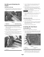
Installing the Handle
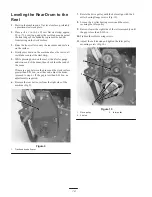
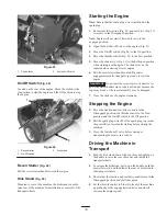
2. Remove the capscrew, washer, and lockwasher from the
mounting pin on each side of the mower, as shown in
Fig. 1.
1
4
2
3
Figure 1
1.
Mounting pins
2.
Handle arms
3.
Capscrew and locknut
4.
Hairpin cotter and ring pin
3. Remove the capscrews and locknuts securing the
bottom of the handle arms to each side of the mower, as
shown in Figure 1.
4. Remove the hairpin cotters and ring pins securing the
handle arms to the rear of the frame (Fig. 1).
5. Insert the handle ends thru the holes in the handle arms
and align the holes with the mounting pins (Fig. 1).
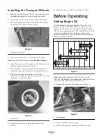
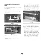
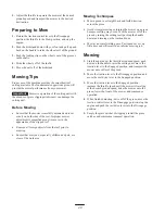
6. Squeeze the handle ends inward and install them on the
mounting pins (Fig. 2).
1
Figure 2
1.
Handle end
7. Secure the handle ends to the mounting pins with the
capscrews, washers, and lockwashers previously
removed (Fig. 2).
8. Secure the bottom of handle arms to each side of the
mower with the capscrews and locknuts previously
removed (Fig. 2). Ensure that you install the bushings in
the handle arm mounting holes.
Important
Do not overtighten the capscrews. The
handle arms must pivot freely.
9. Secure the handle arms to the rear of the frame with the
hairpin cotters and ring pins previously removed
(Fig. 2).
10. Secure the cables to the handle with cable ties.
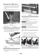
Adjusting the Handle
1. Remove the hairpin cotters from the ring pins on each
side of the mower (FIg. 1).
2. While supporting the handle, remove the ring pins from
each side and raise or lower the handle to the desired
operating position. (Fig. 1).
3. Install the ring pins and hairpin cotters.
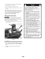
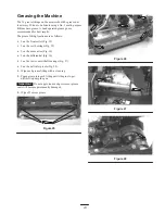
Installing the Kick Stand
Model 04060 only
Note: Fasteners shipped loosely on kick stand.
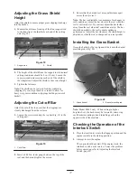
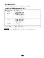
1. Hook spring into hole in spring bracket and onto spring
retainer while aligning kick stand with mounting holes
in rear frame (Fig. 3).
1
2
4
3
Figure 3
1.
Kick stand
2.
Spring bracket
3.
Spring retainer
4.
Spring
2. Mount kick stand to each side of frame with a capscrew,
lockwasher, spacer flat washer and lock nut (Fig. 3).
Spacer to be positioned in kick stand mounting hole.


