background image

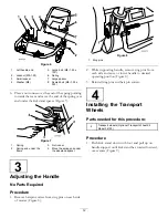
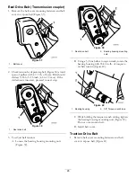
Figure 9

1.

Kick stand

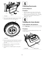
2. Press wheel locking clip toward the center of wheel

and slide wheel onto hex shaft (Figure 10).

Figure 10

1.

Locking clip

3. Rotate wheel back and forth until it slides completely

onto axle and locking clip is secured in groove on
axle shaft.

4. Repeat procedure on opposite side of machine.

5. Inflate the tires to 12-15 psi.

6. Carefully lift up on handle support to release kick

stand.

5

Checking Fluid Levels

No Parts Required

Procedure

1. Check the engine oil level, refer to Checking the

Engine Oil Level in Engine Maintenance , page 22.

2. Check the transmission fluid level, refer to Checking

the Transmission Fluid Level in Drive System
Maintenance , page 25
.

6

Installing the Grass Basket

Parts needed for this procedure:

1

Grass basket

Procedure

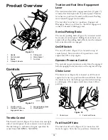
Grasp basket by top lip and slide basket frame into the
receivers (Figure 11).

Figure 11

1.

Grass basket

2.

Basket receivers

13

Содержание 04030

Страница 1: ...r Model No 04030 Traction Unit Serial No 280000001 and Up Model No 04206 Cutting Unit Serial No 280000001 and Up Model No 04031 Traction Unit Serial No 280000001 and Up Model No 04202 Cutting Unit Serial No 280000001 and Up Register at www Toro com Original Instructions EN ...

Страница 2: ...and serial numbers of your product ready Figure 1 and Figure 2 identify the location of the model and serial numbers on the product Write the numbers in the space provided Figure 1 1 Location of the model and serial numbers Traction unit Traction unit Model No Serial No Figure 2 1 Location of the model and serial numbers Cutting Unit Cutting unit Model No Serial No This manual identifies potential...

Страница 3: ...on 17 Preparing to Mow 18 Mowing Operation 18 Maintenance 20 Recommended Maintenance Schedule s 20 Daily Maintenance Checklist 21 Engine Maintenance 22 Engine Oil 22 Servicing the Air Cleaner 23 Replacing the Spark Plug 23 Fuel System Maintenance 24 Cleaning the Fuel Filter 24 Electrical System Maintenance 25 Servicing the Interlock Switch 25 Drive System Maintenance 25 Checking the Transmission F...

Страница 4: ...uel is highly flammable Take the following precautions Store fuel in containers specifically designed for this purpose Refuel outdoors only and do not smoke while refuelling Add fuel before starting the engine Never remove the cap of the fuel tank or add fuel while the engine is running or when the engine is hot If fuel is spilled do not attempt to start the engine but move the machine away from t...

Страница 5: ...afe working condition Never store the equipment with fuel in the tank inside a building where fumes may reach an open flame or spark Allow the engine to cool before storing in any enclosure To reduce the fire hazard keep the engine silencer battery compartment and fuel storage area free of grass leaves or excessive grease Check the grass catcher frequently for wear or deterioration Keep all parts ...

Страница 6: ...ine is running or soon after it has stopped because these areas could be hot enough to cause burns When a person or pet appears unexpectedly in or near the mowing area stop mowing Careless operation combined with terrain angles ricochets or improperly positioned guards can lead to thrown object injuries Do not resume mowing until the area is cleared Maintenance and Storage Check all fuel lines for...

Страница 7: ...perator and are located near any area of potential danger Replace any decal that is damaged or lost 115 1613 1 Warning read the Operator s Manual 3 Thrown object hazard keep bystanders a safe distance from the machine 2 Warning remove the spark plug wire before performing any maintenance on the machine 4 Cutting dismemberment hazard of hand or foot stay away from moving parts 93 9356 1 Entanglemen...

Страница 8: ...64 1 Warning read the instructions before servicing or performing maintenance 2 Cutting hazard of hand or foot stop the engine and wait for moving parts to stop 104 2617 1 Traction drive 4 Forward 2 Reel drive 5 Lever engaged 3 Neutral 6 Lever disengaged 105 2411 1 Transmission oil 8 ...

Страница 9: ...ead the Operator s Manual 3 Thrown object hazard keep bystanders a safe distance from the machine 2 Warning do not operate the machine unless you are trained 4 Warning stay away from moving parts keep all guards in place 9 ...

Страница 10: ...o parts required Adjust the handle 4 Transport wheels Optional Transport Wheel Kit Model 04123 2 Install the transport wheels 5 No parts required Check the engine oil and transmission fluid levels 6 Grass basket 1 Install the grass basket Media and Additional Parts Description Qty Use Operator s Manual 1 Engine Operator s Manual 1 Parts Catalog 1 Operator Training Material 1 Certificate of Complia...

Страница 11: ...ure 1 Kickstand assembly 1 Spring 1 Small spacer 1 Large spacer 1 Large bolt M8 1 25 x 100 1 Small bolt M8 1 25 x 030 2 Locknut M8 x 1 25 2 Washer M8 Procedure 1 Position the kickstand between the tabs on the rear of the frame 2 Install a washer M8 onto the small bolt M8 1 25 x 030 Install the right side of the kickstand to the frame with the bolt and washer the small spacer and locknut M8 1 25 Fi...

Страница 12: ... the kickstand spacer 3 Adjusting the Handle No Parts Required Procedure 1 Remove hairpin cotters from ring pins on each side of mower Figure 8 Figure 8 1 Ring pins 2 While supporting handle remove ring pins from each side and raise or lower handle to desired operating position Figure 8 3 Reinstall ring pins and hair pin cotters 4 Installing the Transport Wheels Parts needed for this procedure 2 T...

Страница 13: ...i 6 Carefully lift up on handle support to release kick stand 5 Checking Fluid Levels No Parts Required Procedure 1 Check the engine oil level refer to Checking the Engine Oil Level in Engine Maintenance page 22 2 Check the transmission fluid level refer to Checking the Transmission Fluid Level in Drive System Maintenance page 25 6 Installing the Grass Basket Parts needed for this procedure 1 Gras...

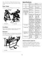
Страница 14: ... the left to engage reel or back to neutral to disengage reel Service Parking Brake The service parking brake Figure 13 is located on left front side of control panel Pulling the lever back over center will set the parking brake Brake must be released before traction drive is engaged On Off Switch The on off switch Figure 13 is located on top of control panel Move switch to On position to start en...

Страница 15: ...with integral lighting coil maximum noise suppression muffler 85 dB A at operator s ear Kawasaki 4 cycle 3 7 2 7 kw air cooled OHV engine 3600 RPM 7 57 cu inch 124 cc displacement cast iron cylinder sleeve electronic ignition with integral lighting coil maximum noise suppression muffler 85 dB A at operator s ear Fuel capacity 2 64 qt 2 5 l regular grade unleaded gasoline 2 64 qt 2 5 l regular grad...

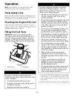
Страница 16: ... gasoline that spills Do not fill the fuel tank completely full Add gasoline to the fuel tank until the level is 1 inch 25 mm below the bottom of the filler neck This empty space in the tank allows gasoline to expand Never smoke when handling gasoline and stay away from an open flame or where gasoline fumes may be ignited by a spark Store gasoline in an approved container and keep it out of the re...

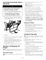
Страница 17: ...osition when starting a cold engine The choke may not be required when starting a warm engine 6 Pull the recoil starter handle out until positive engagement results then pull it vigorously to start the engine Open the choke as engine warms up Important Do not pull recoil rope to its limit or let go of starter handle when rope is pulled out because rope may break or recoil assembly may be damaged S...

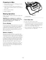
Страница 18: ... the work area Method of Mowing The greens should be mowed in a straight back and forth direction across the green Avoid circular mowing or turning the mower on greens areas since scuffing may occur Turning the mower should be done off the green by raising the cutting reel pushing the handle down and turning on the traction drum Mowing should be done at a normal walking pace Fast speeds saves very...

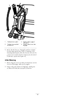
Страница 19: ...ncrease throttle speed until the mower is traveling at the desired ground speed drive the mower out onto the green area lower the front of the mower down and commence operation Figure 20 After Mowing 1 Drive off green move reel drive and traction control levers to Disengage and stop the engine 2 Empty the grass catcher of clippings install grass catcher and commence transport operation 19 ...

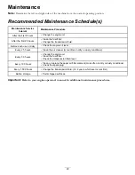
Страница 20: ...ily Check the engine oil level Every 25 hours Clean the air cleaner more often in dirty or dusty conditions Every 50 hours Change the engine oil Clean the fuel filter Check the transmission fluid level Every 100 hours Clean or replace the paper air filter element more often in dirty or dusty conditions Check the spark plug Every 1 500 hours Change the transmission fluid Or 2 years whichever occurs...

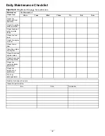
Страница 21: ...ng brake operation Check that pivot joints operate freely Check the fuel level Check the engine oil level Check the air filter Clean the engine cooling fins Check for unusual engine noises Check for unusual operating noises Check the reel to bedknife adjustment Check the height of cut adjustment Touch up damaged paint Notation for Areas of Concern Inspection performed by Item Date Information 21 ...

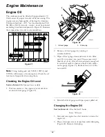
Страница 22: ...rval Before each use or daily 1 Position mower so the engine is level and clean around oil level gauge Figure 22 Figure 22 1 Oil level gauge 2 Drain plug 2 Remove oil level gauge by rotating it counterclockwise 3 Wipe oil level gauge clean and insert it into filler port Do not screw into port Then remove and check level of oil If level is low add only enough oil to raise level until it is between ...

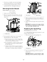
Страница 23: ...oam element to dry but do not twist because the foam may tear C Saturate element with clean engine oil Squeeze element to remove excess oil and to distribute oil thoroughly An oil damp element is desirable Figure 25 1 Foam element 2 Paper element 4 When servicing foam element check condition of paper element Clean or replace every 100 hours or as required 5 Install foam element paper element and a...

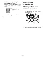
Страница 24: ...rrectly gapped spark plug and tighten firmly to 17 ft lb Figure 27 Fuel System Maintenance Cleaning the Fuel Filter Service Interval After the first 25 hours Every 50 hours 1 Close fuel shut off valve and unscrew bowl from filter body Figure 28 Figure 28 1 Shut off valve 2 Bowl 2 Clean bowl and filter in clean gasoline and install 24 ...

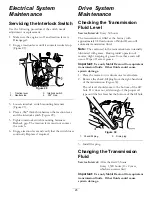
Страница 25: ...led at the factory with approximately 94 fluid ounces of Mobil Dexron lll automatic transmission fluid Note The seals used in the transmission are internally lubricated with grease During initial operation of mower slight weeping of grease from these seals will occur Wipe off excess grease Important Use only Mobil Dexron lll or equivalent transmission fluids Other fluids could cause system damage ...

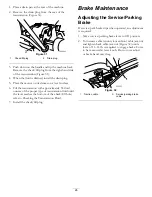
Страница 26: ...uid ounces of the proper type of transmission fluid until the level reaches the bottom of the check fill hole refer to Checking the Transmission Fluid 7 Install the check fill plug Brake Maintenance Adjusting the Service Parking Brake If service park brake slips when operated an adjustment is required 1 Move service parking brake lever to Off position 2 To increase cable tension loosen front cable...

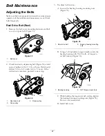
Страница 27: ...3 16 to 5 16 inch 4 8 to 7 9 mm If the deflection is incorrect proceed to next step Figure 34 1 Reel drive belt 3 Driven pulley 2 Drive pulley 3 To adjust belt tension A Loosen the bearing housing mounting nuts Figure 35 Figure 35 1 Reel drive belt 2 Bearing housing mounting nuts B Using a 3 8 inch drive torque wrench rotate the bearing housing with 35 40 in lb of torque to set belt tension Figure...

Страница 28: ...belt 3 To adjust belt tension A Loosen the bearing housing mounting nuts Figure 39 Figure 39 1 Reel drive belt 2 Bearing housing mounting nuts B Using a 3 8 inch drive torque wrench rotate the bearing housing with 35 40 in lb of torque to set belt tension Figure 40 Figure 40 1 Bearing housing 2 3 8 Torque wrench here C While holding the torque wrench setting tighten the bearing housing mounting nu...

Страница 29: ...loosen the bolt securing the idler bracket to the side plate Figure 43 Figure 43 1 Tang washer 2 Idler bracket bolt B Using a 3 8 inch drive torque wrench rotate the idler bracket with 35 40 in lb of torque to set the belt tension Figure 44 While holding the torque wrench setting tighten the idler bracket mounting bolt The tang washer is installed to prevent the belt from slipping Do not over tens...

Страница 30: ...nt cable jam nut 4 Check control operation Adjusting the Reel Control If reel control does not engage or it slips during operation an adjustment is required 1 Make sure traction control is properly adjusted refer to Adjusting the Traction Control 2 To increase cable tension loosen front cable jam nut and tighten back cable jam nut Figure 46 located on top of gear box until the reel cable force add...

Страница 31: ...Figure 48 and rest traction unit on restrained kickstand 6 Pull cutting unit forward about 2 inch 51 mm and then to the right to disengage the transmission coupling Figure 49 Figure 49 1 Transmission coupling 7 Reverse procedure to install cutting unit Note When tightening the pivot arm mounting fasteners use an adjustable end wrench to hold the pivot arm parallel to the side plate Figure 50 Figur...

Страница 32: ...ts and paralleling is not required A limited amount of adjustment is possible by setting the cutting unit on a surface plate and loosening the sideplate mounting bolts Figure 53 Adjust and re tighten bolts Figure 53 1 Sideplate mounting bolts Important Whenever the cutting unit has to be tipped to expose bedknife reel prop up rear of cutting unit to make sure nuts on back end of bedbar adjusting s...

Страница 33: ... reel blades Should excessive reel drag be evident it will be either necessary to backlap or regrind the cutting unit to achieve the sharp edges needed for precision cutting see Toro reel sharpening manual Adjusting the Height of Cut For heights of cut greater than 500 the high height of cut kit must be installed 1 Loosen locknuts securing height of cut arms to cutting unit side plates Figure 56 F...

Страница 34: ...t suited for the desired height of cut Adjusting the Cut Off Bar Adjust cut off bar to assure clippings are cleanly discharged from the reel area 1 Loosen screws securing top bar Figure 59 to cutting unit Figure 59 1 Cut off bar 2 Insert 060 inch feeler gauge between top of reel and bar and tighten screws Ensure bar and reel are equal distance apart across complete reel Note The bar is adjustable ...

Страница 35: ...125 inches Standard 98 7260 Tournament Flex 18 0 125 0 25 inches 110 2300 Extended Microcut Flex 18 0 062 0 125 inches Less Aggressive 110 2301 Low Cut Flex 18 0 25 inches and up Rollers Standard and Optional Part Number Description Mower Diameter Material Comments 107 9037 Narrow Wiehle Flex 21 2 5 inches Aluminum Standard Front 107 9038 Wide Wiehle Flex 21 2 5 inches Aluminum More Penetration 10...

Страница 36: ...rvicing the Bedbar Removing the Bedbar 1 Turn the bedbar adjuster screw counterclockwise to back the bedknife away from reel Figure 61 Figure 61 1 Bedbar adjusting screw 4 Jam nut 2 Spring tension nut 5 Bedbar bolt 3 Bedbar 2 Back out the spring tension nut until the washer is no longer tensioned against the bedbar Figure 62 3 On each side of the machine loosen the jam nut securing the bedbar bolt...

Страница 37: ... drive cover on the left side of reel assembly Figure 64 Figure 64 1 Reel drive cover plug 2 Insert a 18 mm socket onto hex flange nut on left end of reel shaft 3 Backlap according to the procedure in the Toro Sharpening Reel and Rotary Mowers Manual Form No 80 300 PT Contact with the reel or other moving parts can result in personal injury Stay away from the reel while backlapping Never use a sho...

Страница 38: ...gine to distribute conditioned fuel through the fuel system 5 minutes B Either stop engine allow it to cool and drain the fuel tank or operate the engine until it stops C Restart the engine and run it until it stops Repeat on Choke until the engine will not restart D Dispose of fuel properly Recycle as per local codes Note Do not store stabilizer conditioned gasoline over 90 days 3 Check and tight...

Страница 39: ...Notes 39 ...
Страница 40: ...t limited to weather storage practices contamination use of unapproved coolants lubricants additives or chemicals etc Normal wear and tear items Normal wear and tear includes but is not limited to damage to seats due to wear or abrasion worn painted surfaces scratched decals or windows etc Parts Parts scheduled for replacement as required maintenance are warranted for the period of time up to the ...

Отзывы: