background image

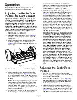
paper being cut or a slight drag when the paper
is pulled.

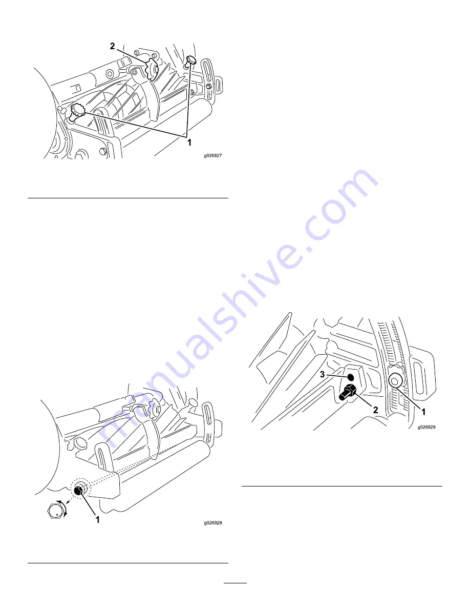
g026927

Figure 5

1.

Throwout knobs

2.

Bedknife adjusting knob

4.

Continue to check for light contact across the full
length of bedknife using paper. If light contact is
not evident, the bedknife is not parallel to the
reel.

5.

Loosen the nut on the left bedbar pivot bolt
enough to ease turning of eccentric bolt.

6.

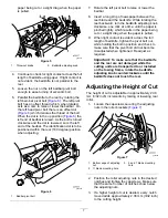
Parallel the bedknife to the reel by rotating the
left bed–bar pivot bolt (

Figure 6

). The left pivot

bolt has an offset thread which, when rotated,
acts as a cam to raise or lower the bedbar. On
the left hand pivot bolt there is an offset dot
(

Figure 6

) which denotes the thread of the bolt.

When the dot is in the up position (

Figure 6

the

left end of bedbar is raised. As the bolt is turned
clockwise and the dot is lowered, so is the left
end of the bedbar. The identification dot is to be
positioned within the rear (180 degree) position
when adjusting.

g026928

Figure 6

1.

Bedbar pivot bolt

7.

Rotate the left pivot bolt to raise or lower the
bedbar.

8.

Insert a long strip of newspaper between the
reel blade and the bedknife. While rotating the
reel backward, turn the bedknife adjusting knob
clockwise, one click at a time, until the paper is
pinched lightly, which results in the paper being
cut or a slight drag when the paper is pulled.

9.

When light contact is evident across the full
length of bedknife, tighten the pivot bolt nut,
while holding the bolt in position and check to
make sure that the pivot bolt did not become
misadjusted when tightened. Readjust as
required.

Important:

To make sure that the bedknife

and the reel are not damaged while the
cutting units are transported to or installed
on the towing frame, rotate the bedknife
adjusting knob counterclockwise until the
bedknife does not touch the reel.

Adjusting the Height of Cut

The height of cut is adjustable in approximately 2.38
mm (3/32 inch) increments by raising or lowering rear
roller.

1.

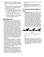
Loosen the capscrews securing the adjusting
nuts in the roller brackets (

Figure 7

).

g026929

Figure 7

1.

Bottom edge of adjusting
nut

3.

5 and 7 blade mounting
hole

2.

11 blade mounting hole

2.

Position the roller adjusting nuts in the desired
notches and tighten the capscrews. Make sure
that the same number of notches show below
the adjusting nuts.

3.

If a higher height of cut is desired, every notch
moved adds approximately 2.38 mm (3/32 inch)
to the cutting height.

7


Содержание 01005

Страница 1: ...Reelmaster 5 7 and 11 Blade Reel Mower Model No 01005 Serial No 403460001 and Up Model No 01007 Serial No 403460001 and Up Model No 01011 Serial No 403460001 and Up Register at www Toro com Original Instructions EN 3429 830 A ...

Страница 2: ...er or Toro Customer Service and have the model and serial numbers of your product ready Figure 1 identifies the location of the model and serial numbers on the product Write the numbers in the space provided Important With your mobile device you can scan the QR code on the serial number plate if equipped to access warranty parts and other product information g282039 Figure 1 1 Location of the mode...

Страница 3: ...ccur Do not put your hands or feet near moving components of the machine Do not operate the machine without all guards and other safety protective devices in place and functioning properly on the machine Keep clear of any discharge opening Keep bystanders and children out of the operating area Never allow children to operate the machine Before you leave the operator s position do the following Par...

Страница 4: ...ades never straighten or weld them On multi bladed machines take care as rotating 1 blade can cause other blades to rotate Safety and Instructional Decals Safety decals and instructions are easily visible to the operator and are located near any area of potential danger Replace any decal that is damaged or missing decal94 6304 94 6304 1 Clutch 3 Turn clockwise to disengage 2 Turn counterclockwise ...

Страница 5: ...ping caps from the wheel hubs Note Keep the shipping caps Install them on the wheel hubs to prevent grinding dust from entering wheel bearing whenever you grind the reel Installing the Wheels 1 Remove the shipping caps from the wheel hubs 2 Install the drive wheels with cap screws and lock washers Figure 3 g026925 Figure 3 Product Overview Specifications Weight 11 Blade 7 Blade 5 Blade All with 0 ...

Страница 6: ...4 Operate the cutting units for 15 to 20 minutes so that the bedknife and reel reach normal operating temperature then stop the operation Next disengage the reel throwout knobs and spin the reel backward A whispering sound not clicking should be emitted and this assures the correct adjustment If a whispering sound is not heard the bedknife and reel must be readjusted refer to steps 3 5 By contrast...

Страница 7: ...e rotating the reel backward turn the bedknife adjusting knob clockwise one click at a time until the paper is pinched lightly which results in the paper being cut or a slight drag when the paper is pulled 9 When light contact is evident across the full length of bedknife tighten the pivot bolt nut while holding the bolt in position and check to make sure that the pivot bolt did not become misadju...

Страница 8: ...the leaf is cut off If the cutting unit is equipped with pneumatic tires pressure must be maintained at 241 3 kpa 35 psi Low tire pressure can cause bedknife to dip into the grass and scalp the turf An uneven cut will likely result Operating Sound A cutting unit that is adjusted correctly gives off a whispering sound when operated If there are buzzing clicking or metallic sounds the cutting unit h...

Страница 9: ...s will eventually develop at both ends of the bedknife These notches must be rounded off or filed flush with cutting edge of bedknife to assure smooth operation 3 Loose Reel Bearings If reel bearings are suspected to be loose check them immediately or extensive damage may result refer to Reel Bearing Adjustment 4 Hitting a Foreign Object The bedknife and the reel cutting edges can be damaged if a ...

Страница 10: ...the roller bracket and the level surface Figure 12 g026926 Figure 12 1 26 cm 10 1 4 inches 2 Filler plug 3 Remove the filler plug from inside of each gear case Figure 12 Check the oil level in the gear case it should be level with the bottom of the filler hole If the oil is level with bottom of the hole install the filler plug Important Check for oil leaks caused by a worn or improperly installed ...

Страница 11: ... the reel or if the cutting unit has been disassembled an adjustment to the reel bearing may be necessary 1 Remove the 4 screws securing the left wheel to the wheel hub and remove the wheel Place the wheel under the gear case for support 2 Raise and block the back of the cutting unit until there is 0 178 to 0 203 m 7 to 8 inches between the bottom of the gear case extending behind the roller brack...

Страница 12: ...he reel Note As the reel blades continue to run against the bedknife a slight burr will appear on the front cutting edge surface the full length of the bedknife If a file is occasionally run across the front edge to remove this burr improved cutting can be obtained If the reel blade edges and the bedknife edge are slightly rounded and do not have severe nicks lapping only with a lapping compound m...

Страница 13: ...per cannot be cut cleanly along the entire length of each reel blade continued lapping is necessary Replacing the Bedknife 1 To replace the bedknife remove the 11 screws holding the knife to the bed bar 2 Remove the rust scale and corrosion from the bedbar surface and apply a thin layer of oil to the bedbar surface 3 Clean the screw threads 4 Apply anti seize compound to the screws and install the...

Страница 14: ...face inboard 2 Replace the bearing cups and insert the bearing cones into the roller 3 Lightly oil the lips of the outer seals Install the outer seals on each end of the roller making sure that the garter springs face inboard 4 Slide 1 sleeve onto the roller shaft against the double jam nuts 5 Wrap the threaded area of the roller shaft with cellophane tape to protect the seals and carefully slide ...

Страница 15: ...Notes ...

Страница 16: ...Notes ...

Страница 17: ...Notes ...

Страница 18: ...l Mower REELMASTER 11 Reelmaster 11 Blade Reel Mower 2006 42 EC Relevant technical documentation has been compiled as required per Part B of Annex VII of 2006 42 EC We will undertake to transmit in response to requests by national authorities relevant information on this partly completed machinery The method of transmission shall be electronic transmittal This machinery shall not be put into servi...

Страница 19: ... for marketing purposes Retention of your Personal Information Toro will keep your personal information as long as it is relevant for the above purposes and in accordance with legal requirements For more information about applicable retention periods please contact legal toro com Toro s Commitment to Security Your personal information may be processed in the US or another country which may have le...

Страница 20: ...tion of the original product warranty and become the property of Toro Toro will make the final decision whether to repair any existing part or assembly or replace it Toro may use remanufactured parts for warranty repairs Deep Cycle and Lithium Ion Battery Warranty Deep cycle and Lithium Ion batteries have a specified total number of kilowatt hours they can deliver during their lifetime Operating r...

Отзывы: