


13
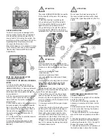
10. During the reassembly of the brush
(6), insert it into the brush base from the
part where the seat is deeper (about 1.5”
40mm). The opposite part with a depth of
about .5” 13,5mm has to be towards the
support plate.
11. Place the support plates (3) and
(4) into their position, then the blocking
support, screw down the knob and insert
once more the stop (2) and finally reposi
-
tion and block the bar of the side rubber
through the stop (1).
ATTENTION:
The brushes must be inserted easily with-
out using tools in order not to damage or
force them.
Use only brushes supplied with the ma-
chine or the ones indicated in the para-
graph “RECOMMENDED BRUSHES”. The
use of other brushes can compromise the
washing result.
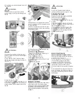
SIDE BRUSH ASSEMBLY AND DISAS-
SEMBLY
The machine is equipped with a side brush
that permits the unit to clean near the right
side borders.
To assemble the brush, the device has to
be in rest position at machine stop.
ATTENTION:
To carry out brushes assembly operations
with the electric supply on, may cause
damages to hands.
ATTENTION:
This operation must be carried out using
gloves to protect from contact with danger-
ous solutions.
1. Keep the push button (1) pressed that
blocks the rotation of the brush plate.
2. Insert the brush into its plate seat un-
derneath the brush base turning it until the
three metal buttons are properly seated
in their slots; rotate the brush to push the
button towards the coupling spring until it
gets blocked.
The figure shows the rotating direction for
the brush coupling. To release it, rotate the
opposite direction.
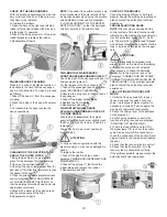
FLOOR CLEANING
RECOVERY TANK
Verify that the squeegee hose couplings
(1/2) are correctly inserted into their seats
and that the exhaust hose plug (4) placed
in the rear part of the machine is well
closed.
Check that the inspection cap (3) placed
on the upper part of the tank is well closed.
Finally, verify the correct tightening of the
closing lever (5) of the cleaning door (6)
placed in the lower part of the tank.
DETERGENT SOLUTION TANK
The capacity of the detergent solution tank
is indicated in the technical data.
Open the screw plug placed in the left part
of the machine and fill the detergent solu
-
tion tank with clean water at a maximum
temperature of 122°F 50°C. Add the liquid
detergent in the percentage and conditions
foreseen by the manufacturer. To avoid ex-
cessive foam presence, which could cause
problems to the suction motors, use the
minimum percentage of detergent. Screw
down the plug to close the solution tank.
The switching on of the signal lamp of low
detergent (19) indicates that the detergent
solution is nearly exhausted.
ATTENTION:
Always use low foam detergent. To avoid
excessive foam, before begining operation,
introduce into the recovery tank a minimum
quantity of anti-foam product.
Never use pure acid.
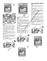
STARTING OF THE MACHINE
A safety device avoids the machine’s
movement if the operator is not seated
correctly.
To switch on the machine:
1. Sit on the seat.
2. Turn the key switch (5) clockwise to
switch on the machine.
3. Check the charge level of the batteries
on the display (1).
4. With the selector (12) in central position
(BREAK WASHING) the transfer opera-
tions of the machine are carried out (see
under paragraph “FORWARD AND BACK-
WARD MOVEMENT").
5. Moving the selector (12) to the left, the
automatic (AUTO) functioning is chosen.
Moving it to the right, the functioning of the
machine becomes manual (MAN):
A. If the selector (12) is in position (AUTO)
the machine activates and deactivates
all the working functions in an automatic
mode (see under paragraph “WORKING
IN AUTOMATIC MODE”).
B. If the selector (12) is in position (MAN)
every function of the machine has to be
activated or deactivated manually (see
under paragraph “WORKING IN MANUAL
MODE”)
https://harrissupplyind.com - To Order Parts Call 608-268-8080


