Tormach, Inc.
P: 608.849.8381 / F: 209.885.4534
tormach.com
TECHNICAL DOCUMENT
Page 12
©Tormach® 2020. All rights reserved.
Specifications subject to change without notice.
TD10487_PCNC440_ATC_Install_1220A
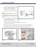
2.
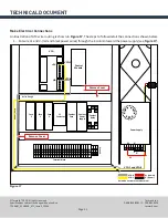
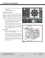
On the power supply, use a Phillips screwdriver to make the following power connections (see
Figure 17
):
•
Insert wire V+ (red) to V+
•
Insert wire V- (black) to V-
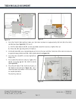
3. Put wire VFD-1 and VFD-8 (yellow and white spindle wires) through the access hole in the bottom of the
Z-column toward the electrical cabinet (see
Figure 17
).
4.
From the electrical cabinet, remove two wire trough covers as shown in
Figure 17
.
5. Put wire VFD-1 and VFD-8 (yellow and white spindle wires) through the wire troughs together toward the
variable frequency drive (VFD) as shown in
Figure 17
.
6. On the VFD, use a small, flat-head screwdriver to make the following spindle connections (as shown in
Figure 17
:
•
Insert wire VFD-1 (yellow) to +5v
•
Insert wire VFD-8 (white) to 2/HA
7.
Replace the wire trough covers inside the electrical cabinet.
8.
Re-install the electrical cabinet cover to the back of the mill using 10 socket head cap screws set aside
earlier.
9. Put the USB cable through the access hole in the bottom of the Z-column toward the back of the stand.
Put the USB cable through the access hole in the back of the stand toward the controller.
10.
On the controller, insert the USB cable into any open USB port.
11.
Re-install the Z-column cover to the back of the mill using eight button head cap screws set aside earlier.
12.
Re-install the motor enclosure’s access plate using four M4 x 6 mm screws set aside earlier.
Validate the Installation
1.
Power on the mill following
Power Off/On
Procedure
detailed earlier in this document.
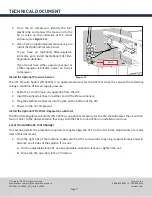
2.
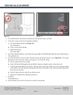
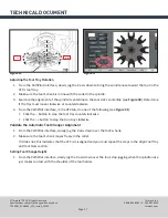
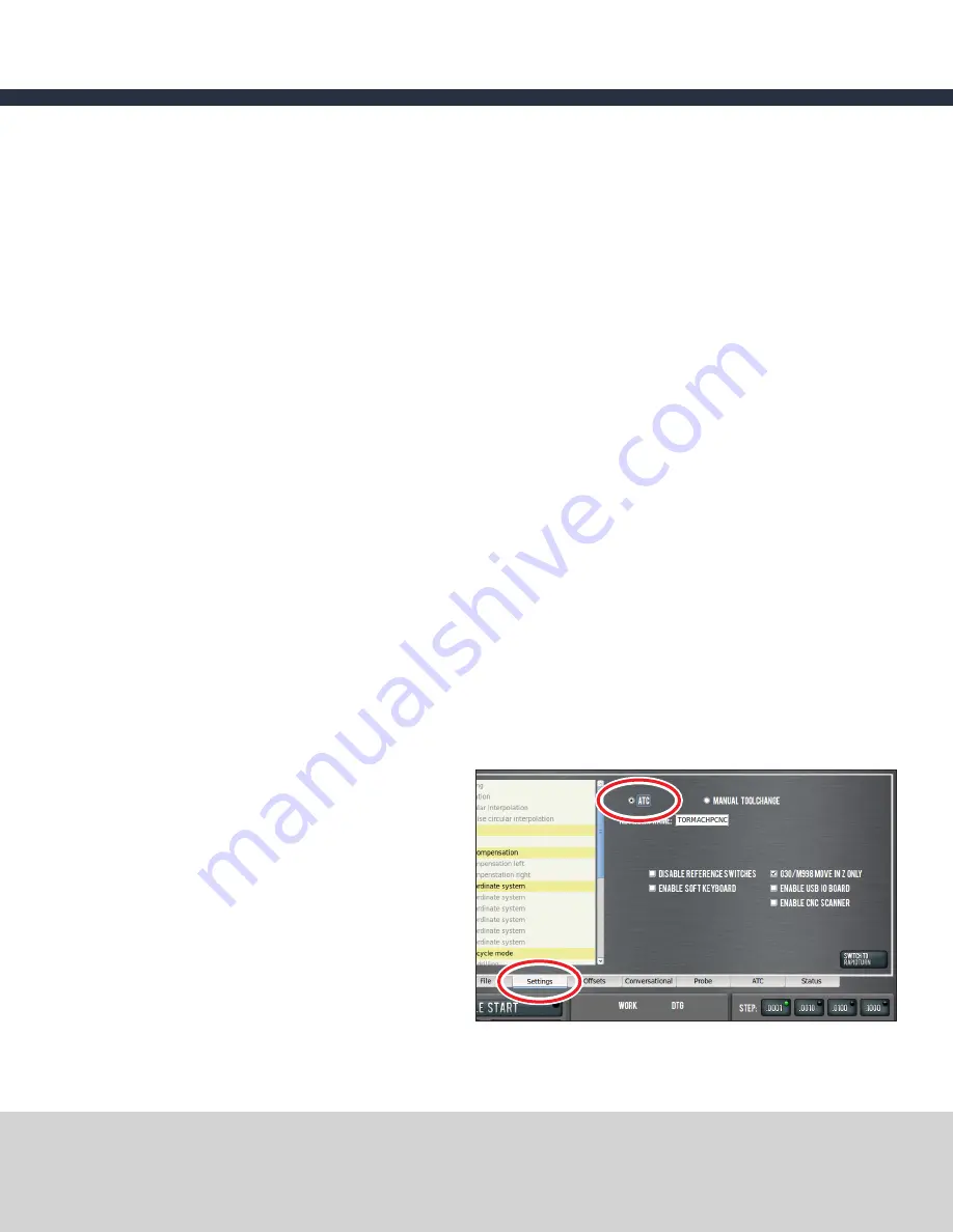
From the PathPilot interface, on the
Settings
tab, select the
ATC
radio button (see
Figure
18
).
The
ATC
tab appears in the PathPilot interface.
Figure 18


