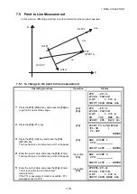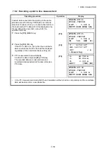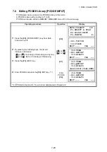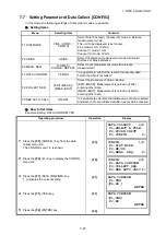
8-11
8 LAYOUT
8.2.1 Layout of Coordinates of Point to Line
The coordinate data of point to line can be used during execution of layout.
When a point name including PTL coordinates (including ‘From’ and ‘To’ data) is specified, the mode
will change to PTL mode automatically.
There are two ways to enter the PTL coordinate data, Direct key input and Data transfer.
Refer to 9.4.2 “PTL (Point to Line) data input” and 9.7 “Data Communications”.
Operating procedure
Operation
Display
1
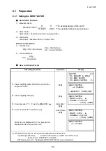
Press the
{F1}
(INPUT) key, and enter PT#.
Press the
{F4}
(ENT) key.
{F1}
Enter PT#
{F4}
2
Enter reflector height in the same way.
When the layout point is set, the instrument will
start layout calculation.
The
{F3}
(PTL) key will be assigned.
Enter R.HT
{F4}
3
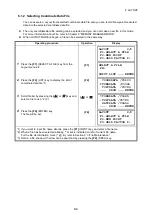
Collimate the prism, and press the
{F1}
(ANGLE)
key.
Collimate P
{F1}
4
Press the
{F1}
(DIST) key.
HD: Measuring (Actual) horizontal distance
dHD: Horizontal distance to be turned to the
layout point = Actual horizontal distance –
Calculated horizontal distance.
dZ: Vertical distance to be turned to the layout
point = Actual vertical distance – Calculated
vertical distance.
{F1}
5
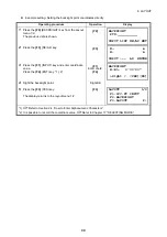
Press the
{F2}
(PTL) key.
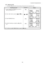
The difference between Collimation point and
Layout point distance on the coordinate system of
the line determined will be displayed.
{F2}
OCC.PT
Offset
From
Layout point
To
Δ
O
Δ
L
Line
E
N
Collimation point
LAYOUT
PT#: PT-21
INPUT LIST NEZ ENTER
REFLECTOR HEIGHT
INPUT
R.HT = 1.500 m
--- --- [CLR] [ENT]
CALCULATED
HR= 45°10'20"
HD= 1.500 m
ANGLE DIST PTL –––
PT#: LP-100
HR: 45°00'00"
dHR: 0°00'00"
DIST ––– PTL –––
HD* 143.84 m
dHD: –13.34 m
dZ: –0.05 m
MODE PTL NP/P NEXT
dL: 0.005 m
dO: 0.327 m
dE: 0.046 m
MODE ANGLE NP/P NEXT

