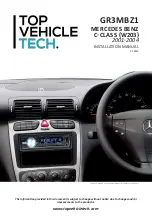
TOP VEHICLE TECH GR3MBZ1 Скачать руководство пользователя страница 3

3

www.topvehicletech.com

FITTING GUIDE

1. Start by loosening the gear shift surround, then using a bojo tool, unclip the centre console trim and pull 

it forward, out of the dashboard.

1. Open the passenger side door and proceed to pull away the door trim from the pillar.

STEREO REMOVAL

DAB ANTENNA INSTALLATION

2. Using a set of panel removal tools, begin to pry away the pillar casing. 

4. The DAB antenna not only has a self adhesive backing, but also features a black earth sheet. When 

placing the DAB antenna, the earth sheet 

MUST

 be placed onto the metal part of the pillar. The antenna 

itself must be located roughly 15cm from the top of the windscreen.

Note: this antenna must not be placed atop any kind of heating elements, this will interfere with the 

antenna’s signal.

5. Once happy with the placement, take the 3m of wiring extension and feed it down through to the 

stereo’s opening. With the wiring adjusted to the appropriate length, feel free to re-install the glovebox. 

3. The glovebox will need to dropped down to route the antennas wiring. To do this you will need to take 

off the side panel and remove 2x screws on the side, 3x screws within the top lip, as well as 2x screws 

underneath. Once free, drop down and leave in the footwell. 

2. With the centre console trim removed, unclip the locater clips located at the front of the ashtray panel. 

When these are loose, simply pull the ashtray out of the dashboard.

FASCIA PLATE SET-UP

1. Take the new fascia and locate it into the dashboard using the pre-existing screws.

3. With the cage secured into place, and once the “

Stereo Installation

” process is complete, simply slide 

the stereo into the fascia and re-assemble the dashboard.

2. Take the pocket and install it into the preferred aperture (most commonly this is installed within the 

bottom port).

3. Unclip the omni-directional fan locator clips within the air vent to allow the vents to excced their normal 

rotation. This will then allow you to remove 2x screws located in the bottom corners of the vent.
4. Once you have removed these screws, use a bojo tool to unclip the top of the air vents and remove it 

from the dashboard.
5. With the top 2x screws removed on the main fascia, now proceed to remove the 2x screws at the very 

bottom of the fascia. Once done, unclip the two clips found next to the screws.
6. Once these 2x locater clips are undone, remove the main fascia whilst disconnecting the wiring.
7. With the fascia out of the way, remove the 2x screws that hold the main radio in place. Once free, 

remove it from the dashboard whilst disconnecting all of the wiring.

Содержание GR3MBZ1

Страница 1: ...d in this document is subject to change without notice due to changes and or improvements to the product s This dash image is a visual representation for display purposes only V1 0522 GR3MBZ1 INSTALLATION MANUAL MERCEDES BENZ C CLASS W203 2001 2004 ...

Страница 2: ...0 30 stereos The wiring harness and interface will help to retain the steering wheel controls with the new stereo Supplied with a 10 Way ISO connector CUSTOMER SUPPORT Installations should be carried out by or under the guidance of an experienced installer If you do encounter any problems during the installation of this product then please contact our dedicated customer service team at Phone 01420...

Страница 3: ...derneath Once free drop down and leave in the footwell 2 With the centre console trim removed unclip the locater clips located at the front of the ashtray panel When these are loose simply pull the ashtray out of the dashboard FASCIA PLATE SET UP 1 Take the new fascia and locate it into the dashboard using the pre existing screws 3 With the cage secured into place and once the Stereo Installation ...

Страница 4: ... Attach the antenna adapter to the vehicles pre existing connection and the back of new stereo 5 Attach the additional wiring on the harness to the back of the stereo Pink Speed Pulse Green Park Brake Purple Reverse 1 Take the steering wheel control interface in hand and connect both the 12 way stereo patch lead and the 14 way steering wheel harness connectors to the corresponding sides 2 Connect ...

Страница 5: ...note configuration layout may differ dependent on vehicle model STEERING WHEEL CONTROL FUNCTIONALITY 1 2 3 4 5 1 Source 2 Track 3 Track 4 Volume 5 Volume 1 Menu Up 2 Arrow Up 3 Arrow Down 4 Volume 5 Volume Original Button New Function ...

Страница 6: ...Pin Connect to Interface Box Interface Box Flying Wires Pink Speed Pulse Green Park Brake Purple Reverse Gear Stereo Patch Lead Connector 12 Pin Connect to Interface Box Note Must be connected first before power connection is made to the interface Stereo Patch Lead Bullet Connector Connect to Steering Wheel Remote Input on back of the stereo WIRING DIAGRAM ...

Страница 7: ...7 www topvehicletech com NOTES ...

Страница 8: ...this manual or any other product then please visit the www topvehicletech com website This manual is considered correct at the time of printing but is subject to change For the latest manuals updates refer to our website Copyright 2022 by TopVehicleTech All rights reserved No part of this publication may be reproduced distributed or transmitted in any form or by any means including photocopying re...

Отзывы: