14
MOUNT THE FIXED LANDING GEAR
❏
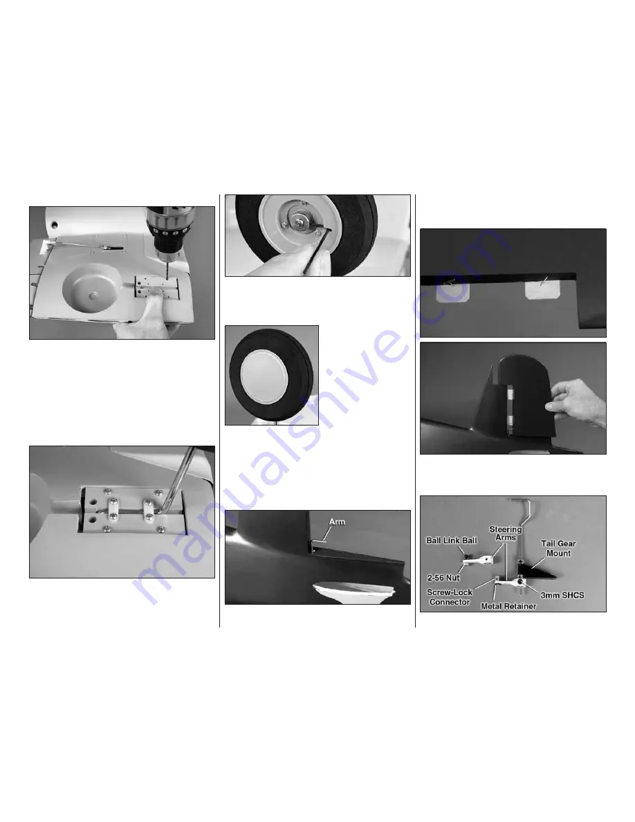
1. Position the fi xed landing gear mounts on the rails
in the wing. Drill 3/32" [2.4mm] holes through the rails
using the holes in the mounts as guides.
❏
2. Enlarge the holes in all four nylon
landing gear
straps
with a 1/8" [3.2mm] drill. Insert the
main landing
gear wires
into the
landing gear mount blocks
, then
secure them with the straps and #4 × 1/2" [12mm]
Phillips screws.
Note:
The “axle” part of the gear wires
face
outward
—toward the respective wing tips.
❏
3. Temporarily mount each block assembly to the
rails with four #4 × 5/8" [16mm] Phillips screws. Remove
the screws, harden the holes with a few drops of thin
CA, allow to harden, then remount the blocks.
❏
4. Mount each wheel with wheel collars on both
sides and 3mm set screws with a drop of threadlocker.
Note the cutout in each wheel to accommodate the
hex key wrench.
❏
5. Snap the wheel
covers into the wheels—
they snap on “hard.”
Make certain the outer
edge of the cover fi ts all
the way down around the
inside of the wheel so
that they will be securely
locked into position. (Also
note the small hole in the
other side of the wheel
for “popping out” the wheel cover with a small piece
of wire.)
ASSEMBLE THE FUSELAGE
INSTALL THE RUDDER
Do not use any glue in the following steps until
instructed to do so.
❏
1. Use coarse sandpaper to roughen the arm portion
of the
rudder torque rod wire
where it goes into the
rudder. Fit the torque rod down through the hole in the
fuselage at the base of the vertical stabilizer and into
the hinge bearing inside.
❏
2. Stick a small T-pin through the middle of two CA
hinges. Insert the hinges into the rudder, then fi t the
rudder to the vertical stab and the torque rod.
Refer to this photo for the following two steps.
Содержание Giant F4U Corsair
Страница 32: ...32 32 Components in Fuselage Components in Wing...
Страница 34: ...34 34...
Страница 35: ...35 Cowl Hole Template For O S 91 4 stroke...
Страница 36: ...Cowl Hole Template For O S 95V...


