


Page 11
1
1
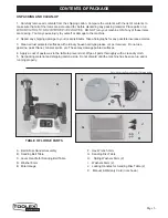
INSTALLING & CHANGING SANDING BELTS
SANDING BELT REMOVAL:
1. Remove the top lock-knob (#52), clear plastic belt
guard (#53), and three Phillips screws (#37) that
secure the side cover (#54) to the sander’s frame.
2. Remove the side cover.
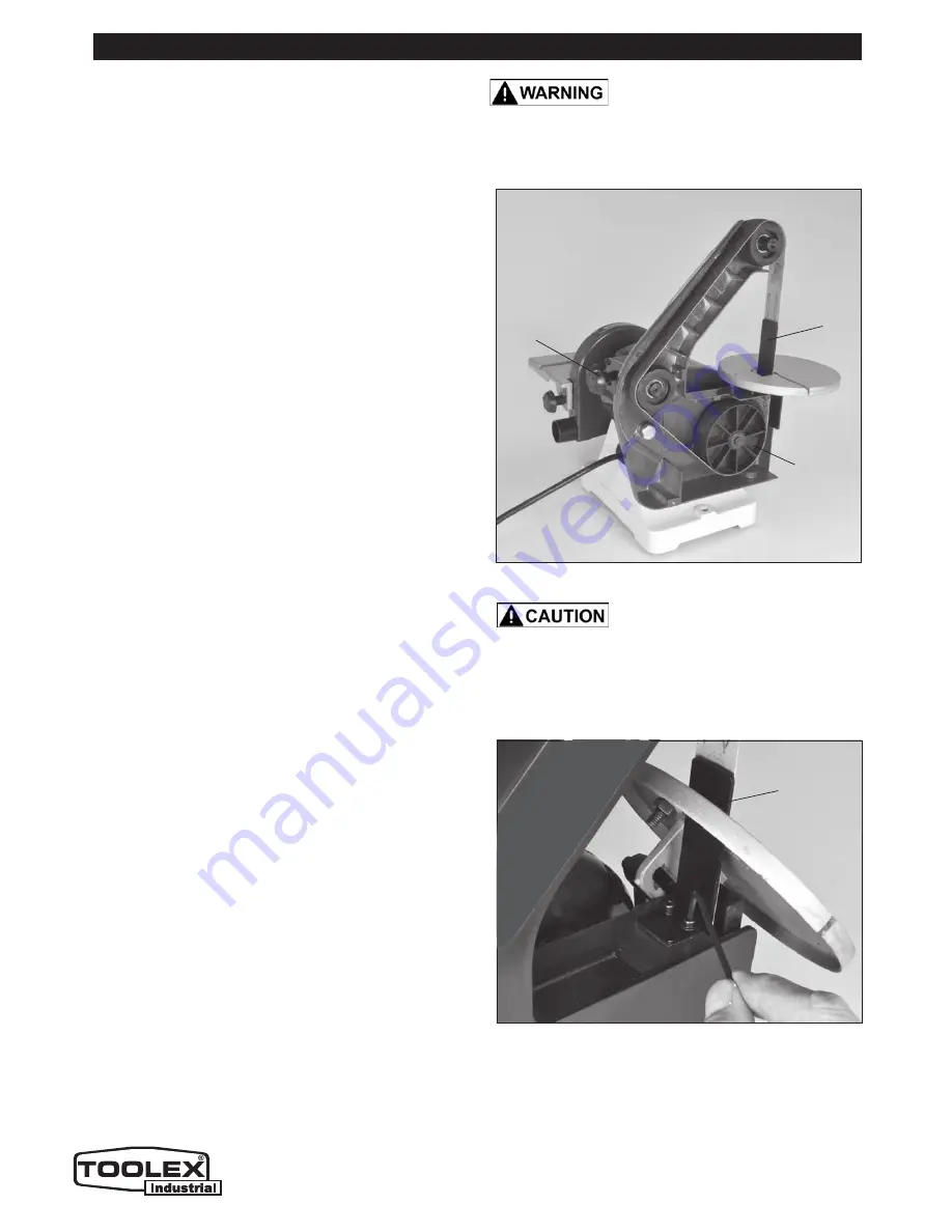
3. Push the tracking knob forward release the
belt tension. FIG. J.
4. Remove the belt from the three wheels.
SANDING BELT INSTALLATION:
5. Install the new belt around the top wheel, the large
drive wheel, and then the rear idler wheel.
NOTE:
the whole spring-loaded tracking knob assem-
bly can be moved/pulled forward to assist in installing
the belt over the last rear idler wheel.
6. Replace the side cover and re-install the 3 Phillips
screws, clear top guard and lock-knob.
7. Before using, check the belt tracking as described
in “Belt Tracking” section, and adjust as necessary.
FIG. J
FIG. K
Never walk away from sander
when machine is running. Always lock the switch in
the ‘OFF’ position and unplug from the power supply
when not in use.
ADJUSTMENTS
THE MACHINE MUST NOT BE
PLUGGED IN AND THE POWER SWITCH MUST BE IN
THE OFF POSITION UNTIL FULL ASSEMBLY AND ALL
ADJUSTMENTS ARE COMPLETE.
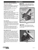
BELT SANDER PLATEN
The platen (# 84) is a heavy steel support plate that
is positioned behind the sanding belt, rising from
the table level to a point several inches above the
table surface. Its purpose is to support the belt when
sanding. The platen should be adjusted so that it is
almost touching the back of the sanding belt. This can
be done by loosening the two hex screws (#86) that
fasten the bottom of the platen to the sander frame. If
the platen is out of alignment for some reason, loosen
these two screws, adjust the platen, and re-tighten the
two screws. FIG. K.
To remove the platen for operations such as curved
surface sanding, stropping, polishing or other special
operations, remove the two screws that fasten the
bottom of the platen to the frame, and remove the
platen.
BELT TRACKING
The belt-tracking adjustment is set at the factory so
that the abrasive belt will run true on the pulleys. If,
however, the belt should track to one side or the oth-
er, an adjustment can be made by turning the tracking
knob (#80), which is located on the back side of the
machine. FIG. J.
- Turning the knob
clockwise
will cause the belt to
track to the right, towards the sander’s frame.
- Turning the knob
counterclockwise
will cause the
belt to track to the left, towards the side guard.
TRACKING
KNOB
DRIVE
WHEEL
PLATEN
PLATEN
SIDE GUARD COVER AND
TOP CLEAR GUARD ARE
REMOVED TO
CHANGE A BELT
Note: Not Actual Toolex Product Pictured below
Содержание 598557
Страница 15: ...Page 15 PARTS DIAGRAM 15 ...


