Communication manual TOHO ELECTRONICS INC.
DWG.No. 4B-6829-A
- 19 -
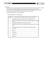
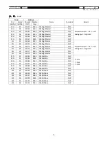
5.2.2.
Structure of Response Message (Data Transmission from This product to Upper Computer)
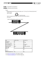
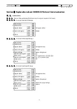
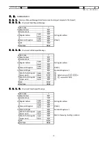
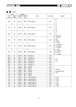
5.2.2.1.
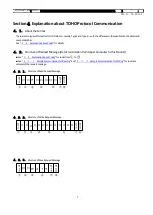
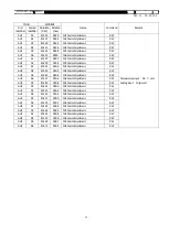
Response Message for Read Request Message
a) Start Code
':'
b) Slave Address
'0','1'
c) Function Code
'0','3'
h) Number of Bytes
'0','4'
Number of Registers x 2
i)
Data for the first register
(Lower word)
Upper
'0','0'
③
Data structure is
①②③④H.
(① represents 1 byte)
Lower
'6','4'
④
Data for the first register
(Upper word)
Upper
'0','0'
①
Lower
'0','0'
②
f) LRC
'9','4'
g) End Code
CR,LF
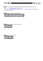
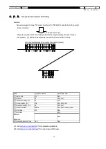
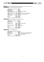
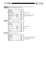
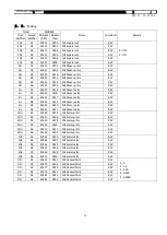
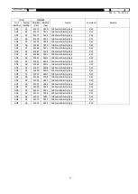
5.2.2.2.
Response Message for Write/Save Request Message
a) Start Code
':'
b) Slave Address
'0','1'
c) Function Code
'1','0'
d) Register Address
Upper
'0','1'
First register address
Lower
'0','0'
e) Number of Registers
Upper
'0','0'
2 (fixed)
Lower
'0','2'
f) LRC
'E','C'
g) End Code
CR,LF
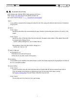
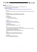
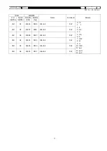
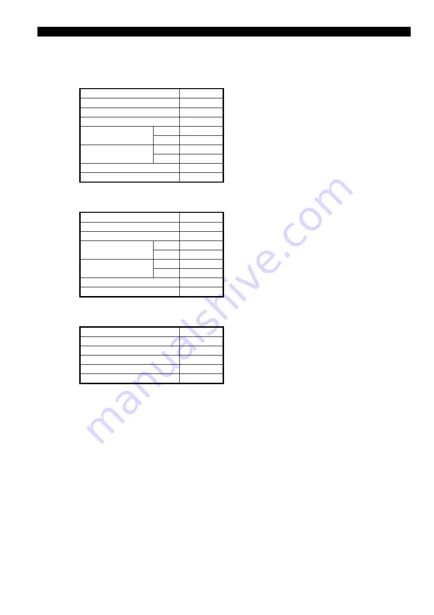
5.2.2.3.
Response message for the error
a) Start Code
':'
b) Slave Address
'0','1'
c) Function Code
'8','3'
← In case of error, the value that is consist
of function code of request message
+ 80H will be set.
j) Error Number
'0','3'
f) LRC
'7','9'
g) End Code
CR,LF


