background image

x

y

2.

3.

5.

Nut

4.

Scharnier


Mounting the Base

01  

Place the shaft of the lumianire on a flat surface - protecting against scratches - and assemble the foot and 

the head of the luminaire.

1. Connect both foot sections together by the hinge.

2. With your thumb, press the plastic plate directly onto foot sections 

at the bottom of the shaft (see diagram). The foot sections will 

automatically move into the correct position, enclosing the shaft 

of the lumiaire without scratching it.

3. Push the connectiing cable in the direction of arrow (see 

diagram) until a loop is formed.

4. Before inserting the clamps, see that both sides have the 

same length of thread (x=y), otherwise it is not possible for 

the foot to embrace the shaft. Apply the correct amount of 

tension: turn part with groove to the left!

5. After employing the clamp, pull the cable 

down so that the clamp does not slip while 

rotating. The clamp will tighten. Use an 

allen key to rotate the chuck axis. 

Insert the key into one of the two 

holes and push down. Move onto 

the second hole and do the 

same. Repeat this porocedu-

re until the foot sections are 

securely connected to the 

shaft. 

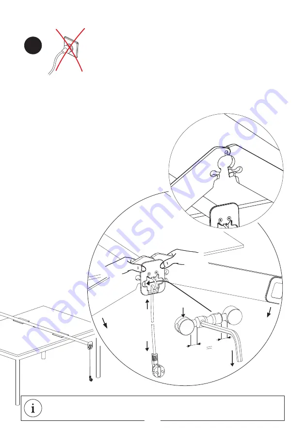
The power plug is used as a circuit breaker and the plug socket 

must be easily accessible.

Mounting the C-BASE on page 22

12

Содержание CC42-0

Страница 1: ...CC42 4 CC42 5 CC42 6 CC42 7 CC42 8 CC42 9 GX42 0 GX42 1 GX42 2 GX42 3 GX42 4 GX42 5 GX42 6 GX42 7 GX42 8 GX42 9 GX43 0 GX43 1 GX43 2 GX43 3 GX43 4 GX43 5 GX43 7 GX43 8 GX43 9 GX20 5 CH20 5 CH42 0 CH4...

Страница 2: ...white BR 06 578 BR 06 1292 GX43 4 XT A TABLE LED OSA white BR 06 991 BR 06 1293 GX43 5 XT A TABLE LED OSA chrome black BR 06 990 BR 06 1060 GX43 7 XT A TABLE LED OSA chrome white BR 06 991 BR 06 1335...

Страница 3: ...BR 06 991 BR 06 1227 BR 14 1011 CX42 5 XT A FLOOR LED OSA chrome black BR 06 990 BR 06 1232 BR 14 1012 CX42 6 XT A FLOOR LED OSA chrome satin BR 06 989 BR 06 1232 BR 14 1012 CX42 7 XT A FLOOR LED OSA...

Страница 4: ...ie den Spanner einsetzen muss auf beiden Sei ten die gleiche L nge des Gewindes zu sehen sein x y da sonst das Verspannen von Fu und Schaft nicht m glich ist Spanner richtig herum einsetzen Drehteil m...

Страница 5: ...ter 01 Zur Montage des XT A TABLE Einbauadapters wird ein 50 mm Loch in einer ausreichend festen Tischplatte ben tigt Der Netzstecker dient der Leuchte als Trennvorrichtung und die Steckdose muss frei...

Страница 6: ...Sie den Leuchtenkopf mit den beiden Schrauben auf dem Schaft Hierbei sollten beide Schrauben gleichm ig fest an gezogen werden W hrend des Anziehens der Schrauben sollte der Leuchtenkopf am vorderen...

Страница 7: ...le nach der Montage des Leuch tenkopfes wieder ber den Leuchtenkopf zu ziehen und zu schlie en Die Leuchte kann trotz der Stoffh lle bereits betrieben werden Stecken Sie den Netzstecker in die Steckdo...

Страница 8: ...tz Bewegungserkennung ausgeschaltet Bei gen gend Umgebungslicht schaltet sich die Leuchte solange aus bis das eingestellte Beleuchtungsni veau unterschritten wird Bei manueller Abschaltung der Leuchte...

Страница 9: ...Funktionsbeschreibung c a 4 m ca 6m 04 Erfassungsbereich des Bewegungsmelders 9...

Страница 10: ...Montage C FU 2x 10...

Страница 11: ...en werden kann wir empfehlen daher Fachbetriebe DEUTSCH Gepr ft und zertifiziert nach europ ischer Leuchtennorm EN 60598 Die lichttechnischen Daten sind im Hersteller neutralen Lichtlabor von DIAL ver...

Страница 12: ...see diagram until a loop is formed 4 Before inserting the clamps see that both sides have the same length of thread x y otherwise it is not possible for the foot to embrace the shaft Apply the correc...

Страница 13: ...he Table Adapter 01 To assemble the XT A TABLE MONO installation adapters a 50 mm hole in a sufficiently solid tabletop is required The power plug is used as a circuit breaker and the plug socket must...

Страница 14: ...e shaft with the two screws Both screws should be evenly tigh tened While tightening the screws of the lamp head the front end should be lightly pushed in the direction of arrow A so that the lamp hea...

Страница 15: ...nely adjusted by turning the levelling screw of the lamp head Rotating the levelling screw in the direction of the arrow DOWN lowers the lamp head rotating it in the direction of arrow UP raises the l...

Страница 16: ...e is sufficient ambient light the luminaire switches itself off and remains switched off until the light level drops below the preset intensity If the luminaire is switched off manually using the swit...

Страница 17: ...Functional Description 03 c a 4 m ca 6m Detection range of the motion sensor 17...

Страница 18: ...Mounting C BASE 2x 18...

Страница 19: ...d personnel ENGLISH The photometric specifications were measuered by multivendor lighting laboratory DIAL EN 12464 Based on EN 12464 the lamp is suitable for workstations PRI AC 120 240V 50 60 Hz SEC...

Страница 20: ...6 1500 G Stand 03 17 Endkontrollnummer 2 Jahre Garantie 5 Jahre Garantie auf die LED Final inspection number 2 years guarantee 5 years guarantee of LED Num ro de contr le final 2 ans de garantie 5 ans...

Отзывы: