


6. INSTALLATION
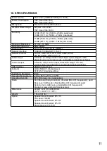
Step 1.
Separate the cable gland components from each
other.
6.1. How to use the Cable Gland
Follow the instructions below when installing the LAN cable.
*Recommended cable:
φ
”4.5~6.0”mm
Step 2.
Pass through RJ-45 connector and caulk cable.
Step 3.
Fix all the components except for the lid.
Step 4.
Close the lid.
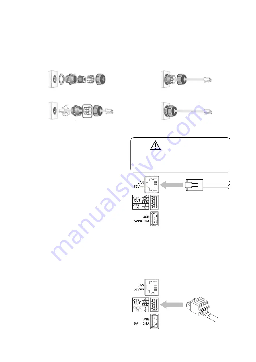
6.2. Network Connection
From PoE/PoE+ switching hub
The US-4SC615 automatically recognizes the
network types(10 BASE-T or 100 BASE-TX) and
start a network connection. For this connection,
use a straight UTP Category 5 or greater LAN
(Ethernet) cable terminated with an RJ-45
connector.
Power can be supplied from the PoE / PoE+
switching hub when this terminal is connected to
it.
In this case, use the switching hub, which is
“IEED802.3af compliant”.
When power is supplied from the PoE switching hub, be
sure to use either PoE/PoE+ (IEEE802.3 af/at).
The use of the switching hub other than the specified one
may cause a fire.
6.3. Terminal Plug Connection
Use the removable plugs supplied with the UC-4SC615 unit to connect the terminals by following the
instructions below
Avoid soldering cable conductor, as contact resistance may increase when the cable is tightened and
the solder is crushed, possibly resulting in an excessive rise in joint temperatures.
[ Recommended Cable ]
SOLID WIRE: 24-16 AWG / 0.51-1.29mm
STRANDED WIRE: 24-16 AWG / 0.205-1.31 mm²
WIRE STRIP LENGTH: 6-8mm
[ CTRL IN ] No-voltage make contact input
Open-circuit voltage: 12 V DC or less
Short-circuit current: 2 mA or less
[ CTRL OUT ] Relay contact output
Withstand voltage: 40 V DC
Control current: 2 to 300 mA
7
CAUTION