background image

34

11.4.  Conference Unit Monitor Volume Setting

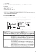
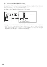
Set the Conference unit’s monitor speaker volume to an appropriate level using the Monitor volume control 

keys. Pressing the [−] key lowers the volume and pressing the [+] key increases the volume. The set volume 

level is displayed by the Monitor volume indicators in 16 steps.*

*The brightness of each LED indicator varies in 3 steps to show 16 steps.

Monitor volume control keys

Monitor volume indicators

Notes

•  During speech, the volume of the Conference unit monitor speaker attenuates to make it easier for the user 

to speak.  

•  The monitor speaker can be muted using a browser if desired because of feedback or other reasons. For 

details, please refer to the separate Instruction Manual (Browser Settings), which can be downloaded from 

the TOA DATA Library (https://www.toa-products.com/international/).

Содержание TS-D1000 Series

Страница 1: ...rchasing TOA s Digital Conference System Please carefully follow the instructions in this manual to ensure long trouble free use of your equipment DIGITAL CONFERENCE SYSTEM TS D1000 SERIES Master control unit Chairman unit Delegate unit ...

Страница 2: ...Specifications and Filenames 20 7 4 Recording to a USB Memory Device 21 7 5 Recording to the Internal Memory 22 8 SYSTEM EXAMPLES 23 8 1 Basic System Example 23 8 2 Expanded System Example Connected Unit Expansion 24 8 3 Expanded System Example Distance Extension 25 9 CONNECTIONS 26 9 1 Power Supply Connections 26 9 2 Signal Ground Connections 26 9 3 Conference Unit and Sub Control Unit Connection...

Страница 3: ...TS D1000 SU Sub Control Unit 39 14 3 TS D1000 EX Extension Unit 39 14 4 TS D1000 CU Chairman Unit and TS D1000 DU Delegate Unit 39 15 SPECIFICATIONS 41 15 1 TS D1000 MU Master Control Unit 41 15 2 TS D1000 SU Sub Control Unit 42 15 3 TS D1000 EX Extension Unit 43 15 4 TS D1000 CU Chairman Unit 43 15 5 TS D1000 DU Delegate Unit 44 15 6 TS D1000 M1 Standard Microphone and TS D1000 M2 Long Microphone...

Страница 4: ...tect smoke or a strange smell coming from the unit If water or any metallic object gets into the unit If the unit falls or the unit case breaks If the power supply cord is damaged exposure of the core disconnection etc If it is malfunctioning no tone sounds To prevent a fire or electric shock never open nor remove the unit case as there are high voltage components inside the unit Refer all servici...

Страница 5: ...t with the power cord connected to the outlet may cause damage to the power cord resulting in fire or electric shock When removing the power cord be sure to hold its plug to pull Use the specified AC adapter for the unit Note that the use of other adapter may cause a fire If dust accumulates on the power supply plug or in the wall AC outlet a fire may result Clean it periodically In addition inser...

Страница 6: ...units that can simultaneously speak can be limited using the Max open mic No restriction function The Mic auto off function automatically turns off the microphone after approximately 30 seconds even if the user forgets to turn off the microphone after speaking Since the Master control unit is provided with its own individual recording function the contents of the conference can be recorded to eith...

Страница 7: ... only Note Refer to Conference Mode Setting on p 31 for details regarding each conference mode 4 Conference mode indicators Green The indicator corresponding to the selected by conference mode selector key 3 lights 5 Max open mic No setting Key Used to set the number of units that can be used simultaneously Max open mic No indicators 1 2 and 8 show the number of Delegate unit who can simultaneousl...

Страница 8: ...s port 17 Access indicator Green Remains continuously lit until a compatible USB memory device is inserted into the USB memory device port 16 Also remains lit during recording to the USB memory device Note Do not remove the USB memory device or turn OFF the power while this indicator is lit 18 USB memory device indicator Green Lights when the inserted USB memory device is ready for recording 19 In...

Страница 9: ...n Lights when the TS D1000 MU is connected to a network and flashes during data transmission reception 33 Recording output terminals 10 dB 10 kΩ unbalanced RCA pin jack x 2 Connect to external recording devices such as IC recorders The same sound output is delivered to both jacks so that simultaneous recordings can be made using two recording devices 34 Line output terminal 10 dB 10 kΩ unbalanced ...

Страница 10: ...vice Noise output should be greatly reduced Note This is not a protective ground connection 3 Cable clamp Route the power cable through this clamp to prevent the AC adapter plug from accidentally being disconnected 4 DC inlet Insert the power plug from the unit s supplied AC adapter into this inlet 5 Conference unit connection terminals RJ45 3 Connect conference units to these terminals using CAT5...

Страница 11: ...unting holes Mounting holes for 3 mm 0 12 diameter screws Use these holes when attaching the unit to a wall or other surface Note Please note that the mounting screws themselves are not supplied with the unit 3 Conference unit connection terminals RJ45 2 When extending the distance between two Conference units connect to either of these terminals using a CAT5e STP LAN cable Tip Either terminal may...

Страница 12: ...can be used Sound from both external microphone and video conference inputs are also muted The key has 2 different operating modes PTT mode and ALT Factory preset to PTT mode PTT mode Microphone turns ON only while the Talk key is pressed ALT mode Microphone turns ON when the Talk key is pressed and OFF when pressed again If Chime is set to sound a chime tone sounds when the key is pressed Factory...

Страница 13: ...t side earphone output Bottom 10 11 12 11 Right side Left side Cover The figure which took off the cover 8 9 9 8 Connection terminal cover Detach this cover when connecting Conference units to the Conference unit connection terminals 9 After completing connection replace the cover where it was 9 Conference unit connection terminals RJ45 x 2 Connect these terminals to the Conference unit connection...

Страница 14: ...is in use during speech 3 Talk key When this key is pressed both the Speech indicator 2 and the Microphone in use indicator 6 light and the microphone turns on Pressing this key again turns off both indicators and the microphone 4 Power indicator White Lights when the power is switched ON 5 Microphone Use either the TS D1000 M1 Standard microphone or TS D1000 M2 Long microphone 6 In use indicator ...

Страница 15: ...t side earphone output Bottom Cover The figure which took off the cover 7 8 8 10 9 11 10 Right side Left side 7 Connection terminal cover Detach this cover when connecting Conference units to the Conference unit connection terminals 8 After completing connection replace the cover where it was 8 Conference unit connection terminals RJ45 x 2 Connect these terminals to the Conference unit connection ...

Страница 16: ...two Chairman units can always be used for speaking regardless of Max open mic No restrictions Priority speech excepted Tips Monitor speaker sound volume is automatically attenuated whenever both the Speech and the microphone s In use indicators are lit Speaker volume can also be muted in the browser settings For details please refer to the separate Instruction Manual Browser Settings which can be ...

Страница 17: ...ease refer to the separate Instruction Manual Browser Settings Notes During Chairman unit priority speech sound output from connected wired microphones and the video conference system are muted In the case of systems configured with multiple Chairman units if one Chairman unit has initiated Priority speech other Chairman units cannot initiate Priority speech even if their Priority speech keys are ...

Страница 18: ... Chairman unit Priority speech sound output from connected wired microphones and the video conference system are muted In the case of systems configured with multiple Chairman units if one Chairman unit has initiated Priority speech other Chairman units cannot use Priority speech even if their Priority speech keys are pressed Step 3 After speaking is finished press the Priority speech key again Bo...

Страница 19: ...ble force to the port Failure to observe this instruction could lead to failure of the TS D1000 MU or damage to the PC or other devices Ensure that the USB memory device is removed when moving the TS D1000 MU from one place to another Moving the TS D1000 MU with such devices inserted could cause failure to the TS D1000 MU or damage to the USB memory device Be sure to back up recorded internal memo...

Страница 20: ... filename indicating the Year Month Date Hour Minute and Second of the time that the recording was started is automatically assigned to each file as follows Sound source filename YYYYMMDD_HHMMSS mp3 Example In the case of a recording started at precisely 10 o clock AM on January 1 2020 the filename 20200101_100000 mp3 is assigned when the recording is stopped When a recording is continuously made ...

Страница 21: ...ss the Recording START key Recording begins The Recording status indicator lights red and the Access indicator lights green Important Do not remove the USB memory device during recording as the recording will be interrupted and the sound source file being recorded could be lost Tip If the USB memory device s remaining recordable time falls to less than one hour the Remaining USB memory capacity wa...

Страница 22: ...o the Internal Memory 7 5 1 Procedure for recording to the internal memory Internal memory indicator 1 2 3 Recording STOP key Recording START key Recording status indicator Step 1 Confirm that no USB memory device is inserted in the USB memory device port and that the Internal memory indicator is lit green Step 2 Press the Recording START key Recording begins and the Recording status indicator lig...

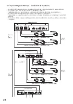
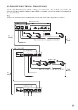
Страница 23: ...e units can be connected to the Master control unit See the Basic System Example below To connect more Conference units 33 to 246 add as many Sub control units as required to support the total number of Conference units See Expanded System Example Connected Unit Expansion on the next page To extend the maximum distance of Conference unit connectivity add the Extension unit See Expanded System Exam...

Страница 24: ...ain The maximum distance from each Sub control unit to the last Conference unit in the daisy chain is 50 m 164 04 ft The maximum distance between the Master control unit and a Sub control unit or between Sub control units is 1 m 3 28 ft Up to 3 lines Up to 2 lines Max 5 units Max 1 m or 3 28 ft Max 1 m or 3 28 ft Max 50 m or 164 04 ft Max 16 Conference units Max 50 m or 164 04 ft Max 16 Conference...

Страница 25: ...in systems in which the number of connected units has been increased Note Only one TS D1000 EX can be connected per line It may be connected in any position on the line Master control unit Sub control unit Sub control unit Up to 2 lines Up to 3 lines Max 50 m or 164 04 ft max 50 m or 164 04 ft Max 50 m or 164 04 ft max 50 m or 164 04 ft Extension unit Extension unit Max 1 m or 3 28 ft Max 1 m or 3...

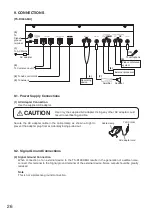
Страница 26: ...ound Connections 2 Signal Ground Connection When connection of an external device to the TS D1000 MU results in the generation of audible noise connect this terminal to the Signal ground terminal of the external device Noise output should be greatly reduced Note This is not a protective ground connection Cable clamp To DC inlet AC adapter cord Recording device To microphone Speaker 5 To network 4 ...

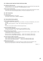
Страница 27: ... Note The same sound output is directed to both left and right channels 7 External Amplifier Connection Output from the TS D1000 MU can be input to an external amplifier or mixer Line output specifications 10 dB 10 kΩ unbalanced phone jack monaural 8 External Processor Connection In cases where feedback cannot be controlled by the internal FBS function a graphic equalizer or other external process...

Страница 28: ...ack mounting bracket to both sides of the TS D1000 MU Use the screws and washers removed in Step 1 Step 3 Mount the TS D1000 MU equipped with the mounting brackets in the rack Use the rack mounting screws and fiber washers supplied with the rack mounting bracket Side panel Washer 6 pcs Screw 6 pcs Fiber washer for M5 supplied with the MB TS920 Four of the removed screws and washers in Step 1 2 Rac...

Страница 29: ...pping screw 3 x 8 1 Rack mounting two units Use the MB 15B J Bracket kit Note The MB 15B J Bracket kit cannot be used to connect the TS D1000 SU to other equipment components for rack mounting Tapping screw 3 x 14 2 Rack mounting bracket 2 Fiber washer for M5 2 Rack mounting screw 5 x 12 2 Tapping screw 3 x 14 2 Oval head screw M3 x 6 2 Coupler 2 TS D1000 SU TS D1000 SU 1 Component parts of MB 15B...

Страница 30: ... Conference units displaying flashing microphone s In use indicators are correctly connected If any units have Microphone indicators that do not flash check the connection between the unresponsive Conference unit and its microphone as well as the connection between that Conference unit and the Master control unit or Sub control unit Step 3 Press the Connection test key again for 3 seconds to termi...

Страница 31: ...ic No that unit cannot be used for speaking first in first out priority The Chairman unit can start speaking at any time up to 2 Chairman units Override Permits speaking to start anytime the Talk key is pressed When the Talk key is pressed if its Conference unit exceeds the preset Max open mic No the unit that first started speaking is forced to terminate speaking allowing the last operated unit t...

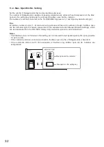
Страница 32: ...ser When set to numbers 3 though 7 all Max open mic No indicators light For details please refer to the separate Instruction Manual Browser Settings which can be downloaded from the TOA DATA Library https www toa products com international Notes The Chairman unit is not included in this setting as it can be used to start speaking at any time only possible for up to 2 units If the conference mode i...

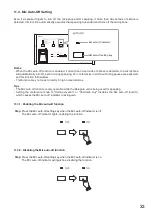
Страница 33: ...function to Disabled This function may not work correctly in high noise locations Tips The Mic auto off function is only operable while the Delegate unit is being used for speaking Setting the conference mode to Voice activation or Chairman only disables the Mic auto off function which causes the Mic auto off indicator to extinguish 11 3 1 Enabling the Mic auto off function Step Press the Mic auto...

Страница 34: ...s The brightness of each LED indicator varies in 3 steps to show 16 steps Monitor volume control keys Monitor volume indicators Notes During speech the volume of the Conference unit monitor speaker attenuates to make it easier for the user to speak The monitor speaker can be muted using a browser if desired because of feedback or other reasons For details please refer to the separate Instruction M...

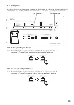
Страница 35: ...g lock key Keys to be locked 11 5 1 Enabling the setting lock function Step Press the Setting lock key for 3 seconds or more when the Setting lock indicator is off The Setting lock indicator lights disabling all settings related key operations 11 5 2 Cancelling the Setting lock function Step Press the Setting lock key for 3 seconds or more when the Setting lock indicator is lit The Setting lock in...

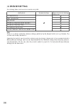
Страница 36: ...nit s monitor speaker on off Note There is no priority relationship between settings performed by the Master control unit or a browser The contents last set take precedence Regarding the method used to perform settings using the browser please refer to the separate Instruction Manual Browser Settings which can be downloaded from the TOA DATA Library https www toa products com international On this...

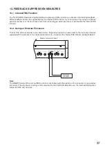
Страница 37: ...internal FBS function 13 2 Using an External Processor Connect the external processor as shown below Regarding operation please refer to the instruction manual supplied with the processor If an external processor is connected the internal FBS function will be disabled Master control unit rear External processor Note The ON OFF status of the internal FBS function is interlocked with the existence o...

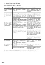
Страница 38: ...cording capacity is insufficient the Internal memory remaining capacity warning indicator lights and the Internal memory indicator extinguishes Delete any files recorded to the internal memory from the browser to create sufficient free space then make a recording after ensuring that the Internal memory indicator lights green Refer to the separate Instruction Manual Browser Settings Internal memory...

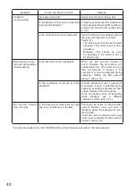
Страница 39: ...aster control or Sub control unit it is connected to Correctly connect the Extension unit to the Master control or Sub control unit Symptom Cause and Points to Check Remedy Power not supplied Is power supplied to the Master control unit Sub control unit or Extension unit Turn ON the Master control unit s power and connect the AC adapters supplied with both the Sub control unit and the Extension un...

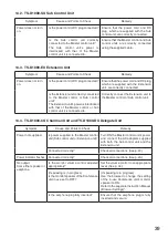
Страница 40: ...ion is set to Enabled the microphone will automatically turn off if silent for more than 30 seconds If pauses of 30 seconds or more are expected during speaking disable the Mic auto off function See p 33 Is the conference mode set to Voice activation In Voice activation mode if a pause of 2 seconds or more is detected during speaking speaking is assumed to have ended turning off the microphone If ...

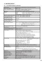
Страница 41: ...r Power indicator Conference mode indicator Max open mic No indicator Mic auto off indicator Monitor volume indicator Connection test indicator External control indicator Setting lock indicator Recording status indicator Access indicator USB memory device indicator Internal memory indicator USB memory device remaining capacity warning indicator Internal memory remaining capacity warning indicator ...

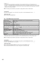
Страница 42: ...nce units Terminal RJ45 connector 3 Sub Control Units Terminal RJ45 connector 2 Maximum Cable Distance 50 m or 164 04 ft between this unit and Conference unit at the end of daisy chain LED Indicator Power indicator Operating Temperature 0 to 40 ºC 32 to 104 ºF Operating Humidity 90 RH or less no condensation Finish Panel Aluminum black 30 glossy paint Case Surface treated steel plate black 30 glos...

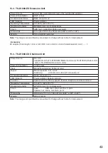
Страница 43: ...15 4 TS D1000 CU Chairman Unit Power Source 24 V DC supplied from the TS D1000 MU Master control unit TS D1000 SU Sub control units or TS D1000 EX Extension units Power Consumption 1 5 W or less Input Microphone terminal XLR 3 31 type Output Monitor speaker 8 Ω 0 4 W Earphone ø3 5 mm mini Jack 3P monaural x 2 Connecting Terminal RJ 45 connector x 2 LED Indicator Power indicator Speech indicator Fu...

Страница 44: ...ation Finish Case ABS resin black mat finish paint Speaker net Black mat finish paint Dimensions 208 9 w x 71 3 h x 160 5 d mm 8 22 x 2 81 x 6 32 Weight 875 g 1 93 lb Note The design and specifications are subject to change without notice for improvement 15 6 TS D1000 M1 Standard Microphone and TS D1000 M2 Long Microphone Model No TS D1000 M1 TS D1000 M2 Type Electret condenser microphone Directiv...

Отзывы: