


4
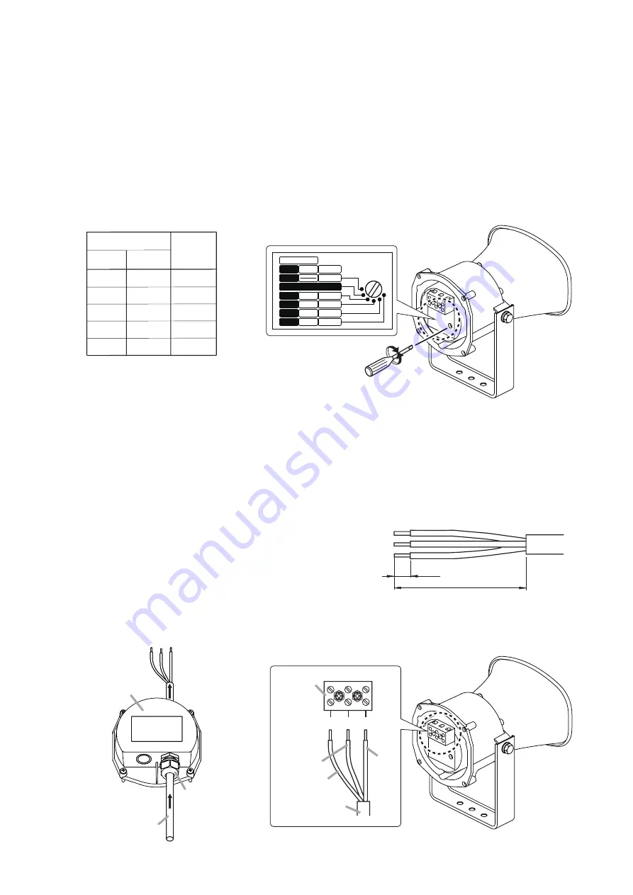
3. IMPEDANCE CHANGE
Input impedance is factory-preset to 670
Ω
.
To change the impedance, change the rear panel-mounted rotary switch position using a standard
screwdriver.
Notes
• This speaker is designed to be used for high impedance applications (70 V/100 V). Never connect the
speaker to low impedance line.
• No sound is output from the speaker when the switch is set to the OFF position.
Caution
Never set the switch to "–" position for 100 V line operation, as doing so may result in damage to the speaker.
100 V
70 V
Imp.
—
330 Ω
670 Ω
1 kΩ
2 kΩ
3.3 kΩ
15 W
10 W
5 W
3 W
15 W
7.5 W
5 W
2.5 W
1.5 W
Line Voltage
Bold figures represent factory-preset values.
LINE VOLTAGE
70V
100V
IMP.
15W
7.5W
5W
2.5W
1.5W
3W
5W
10W
15W
330Ω
670Ω
OFF
1kΩ
2kΩ
3.3kΩ
4. WIRING
The terminal cover is not mounted to the speaker unit when shipped from the factory.
Note
To complete speaker installation, be sure to attach the terminal cover after finishing cable connections.
If the unit is left without the terminal cover attached, water or moisture may get inside the speaker, causing the
unit malfunction.
4.1. When No Bridge Connection is Required
Step 1.
Strip the speaker cable jacket as shown at right.
Step 2.
Run the speaker cable through the cable gland.
Step 3.
Connect the speaker cable according to the polarity indication at the screw terminal.
55 (2.17)
8
(0.31)
Unit: mm (in)
Terminal cover
Speaker cable
Cable gland
2
EARTH HOT COM
COM
HOT
EARTH
Screw
terminal
Speaker cable
3


