


•
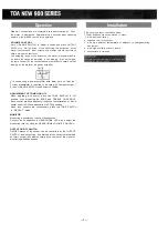
This amplifier has six INPUT PORTS for PLUG-IN MODULES.
Select the desired ones for each application.
•
Plug the modules into INPUT PORTS, sliding them between the
guide rails, and secure each with two screws.
•
When not all INPUT PORTS are occupied, cover the vacant
PORTS with blank panels, and secure them with screws.
•
PLUG-IN MODULES are provided in the following:
Balanced low impedance microphone
preamp module (with presettable low-cut
filter, high-cut filter and gain controls)
Balanced low impedance microphone
preamp module (with presettable low-cut
filter and gain controls)
Equalized mag. phono preamp. module
(with presettable gain control)
Unbalanced high impedance auxiliary
preamp module (with presettable
gain control)
Balanced 10k
Balanced 600
bridging transformer module
line matching
transformer module
Balanced paging input module
(with presettable gain control and MUTE Delay)
Balanced 600
line output module
(with presettable gain control)
Signal tone generator module
(with presettable output level control)
1 kHz sine wave
Yelp and buzzer
One-tone chime and continuous one-tone chime
H-01, H-21, H-31
H-02,H-22, H-32
E-01 , E-11
X-01, X - 1 1 , X-21
B-01, B-11
L-01, L-11, L-41
I-01
T-01
S-01
S-02
S-03
*With H-21, H-22 and X-21 modules employing volume remote
control functions, connecting a potentiometer (10k ohms) to the
terminal of any of these modules permits the sound volume to be
remotely controlled by means of the connected potentiometer.
* H-31 and H-32 modules incorporate muting functions. If a switch
is connected to MUTE TERMINAL on the rear panel of the ampli-
fier and closed, these input signals can be passed through. When
the switch is opened, the input signal is muted.
* E-11 , X-11 , B-11 and L-11 modules incorporate muting functions.
If a switch is connected to MUTE TERMINAL on the rear panel
of the amplifier and closed, these input signals can be muted.
* L-41 incorporates signal activated muting function. Incoming
input signal causes mute terminal to be grounded.
* T-01 is used to feed out mixed signals to external equipment.
*T-01 should be inserted only in INPUT PORT
#5
or
#6.
(See PLUG-IN MODULES for details)
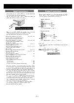
•
Connect power a m p l i f i e r ( s ) to the output terminal of M-900A.
Select 600
or 150
connection, provided at the output ter-
minal, to match the input impedance of a m p l i f i e r ( s ) .
•
AUX OUT
For this connection, use a Phone Plug (Double pole) with two-wire
shielded cable.
600-ohm Connection
Strap terminals 2 and 3 .
4
3
2
1
GND
Hot
Common
Earth
150-ohm Connection
4
3
2
1
GND
Hot
Common
Earth
Strap
terminals 1 and 2 , 3 and 4 .
Hot
Common
Earth
Input Connections
Output Connections
External equipment such as
tape recorders, etc.
— 2 —
Содержание M-9000
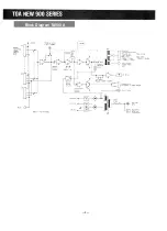
Страница 6: ...Block Diagram M 900 A 5...
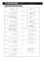
Страница 10: ...Block Diagrams Plug in Modules 10...
Страница 13: ...Schemiatic M 900 A...