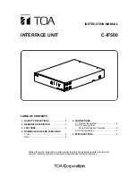
Toa C-IF500 Скачать руководство пользователя страница 8

Printed in Japan
133-12-742-1E

6. SPECIFICATIONS

Notes
• The unit cannot be used in the system with the transmission/reception switching interval of 2 bytes or less or

where transmission signals could be simultaneously sent out from multiple slave terminals.   

• The design and specifications are subject to change without notice for improvement. 

*

1

Communications cannot be made between slave terminals. 

*

2

Applies to the system where the unit and Combination camera are connected in a matched pair.
Represents the total of connected cable distances if multiple Combination cameras or Interface units are
connected in the system (when the CPEV-S cable thicker than 0.65 mm in diameter is used).

• Optional Equipment

MB-15B-BK Rack mounting bracket (for rack mounting one C-IF500 unit)
MB-15B-J

Rack mounting bracket (for rack mounting two C-IF500 units) 

Power Source 

12 V DC 

Current Consumption 

100 mA

External Control

Master: RS-485, screwless connector,

terminating resistance (100 

) switch ON/OFF

Slave*

1

: 4 channel, RS-485, screwless connector, RS-232C, 

D-sub connector (9-pin, male) 

Display 

Power LED indicator, communication LED indicators (TX, RX)

Maximum Cable Distance

RS-485:

1.2 km*

2

RS-232C: 10 m

Communication Speed 

4800 bps, 9600 bps, 19200 bps, 38400 bps

Operating Temperature 

–10 to +50°C 

Operating Humidity 

Under 90% (no due condensation produced) 

Finish 

Panel: Aluminum, black (30% glossy), paint

Case: Pre-coated steel plate, black (30% glossy) 

Dimensions 

210 (w) x 46 (h) x 284.1 (d) mm 

Weight 1.4 

kg

Содержание C-IF500

Страница 1: ...TIONS Front 4 Rear 4 5 CONNECTIONS 5 1 System Examples 5 5 2 Connecting 32 or More Combination Cameras 6 5 3 Star Connection 7 6 SPECIFICATIONS 8 Please follow the instructions in this manual to obtai...

Страница 2: ...the unit If they accidentally spill into the unit this may cause a fire or electric shock Do not insert nor drop metallic objects or flammable materials in the ventilation slots of the unit s cover a...

Страница 3: ...lt in fire or electric shock When the Unit is in Use Do not place heavy objects on the unit as this may cause it to fall or break which may result in personal injury and or property damage In addition...

Страница 4: ...used in the OFF position depending on the connection method Refer to p 6 for details 10 RS 232C terminal SLAVE RS 232C Converts the data received at the Master Connection Terminal into the RS 232C si...

Страница 5: ...oller C IF500 5 5 CONNECTIONS 5 1 System Examples Example 1 Combination camera Monitor TV Multi switcher Remote controller C IF500 Example 2 Bottom TOA Corporation model C IF500 120 MADE IN JAPAN 12V...

Страница 6: ...iameter If multiple cameras are connected to a single terminal the total of each cable distance between connected equipment must be 1 2 km or less Termination switch setting Set the unit s termination...

Страница 7: ...ination switch ON Ch 2 Termination switch ON Ch 3 Termination switch ON Ch 4 Termination switch ON Ch 5 Termination switch ON Ch 6 Termination switch ON Ch 7 Termination switch ON Ch 8 Termination swi...

Страница 8: ...PEV S cable thicker than 0 65 mm in diameter is used Optional Equipment MB 15B BK Rack mounting bracket for rack mounting one C IF500 unit MB 15B J Rack mounting bracket for rack mounting two C IF500...

Отзывы: