background image

8 Ω

13 kΩ

6.7 kΩ

3.3 kΩ

1.7 kΩ*

0

COM

Earth

HOT

COM

Earth

HOT

COM

Matching 
transformer 

Screw terminals

Thermal fuse
(84 ºC or 183.2 ºF)

* Factory-preset

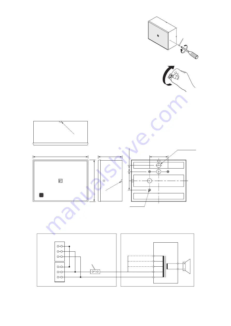
5. WIRING DIAGRAM

R6 (0.24)

250 (9.84)

190 (7.48)

83.5 (3.29)

28.3 (1.11)

108 (4.25)

3-ø20 (0.79)

3-ø5 (0.2)

83.5 (3.29)

R6 

(0.24)

4

Step 4.

Hook 2 V-shaped springs attached to the baffle into the slotted
holes of the cabinet, push the baffle onto the cabinet, then fix
the supplied tapping screws 3 x 16 on both sides.

Note

When the speaker mounting orientation is vertical, pinch and
rotate the logo mark on the baffle into the right position.

4. DIMENSIONAL DIAGRAM

Unit: mm (in)

Tighten

Tapping screws 
3 x 16 (accessory)

Содержание BS-678BSB

Страница 1: ...sive technical knowledge and experience The speaker may fall off if incorrectly installed resulting in possible personal injury Install the speaker only in a location that can structurally support the full weight of the unit and mounting bracket Doing otherwise may result in the speaker falling down and causing personal injury and or property damage Since the unit is designed for in door use do no...

Страница 2: ...parts they could deteriorate and cause the speaker to fall possibly resulting in personal injury Do not install the speaker in indoor swimming pools or such locations where liquid chemicals are used The parts deteriorate if corroded causing the speaker to fall which could result in personal injury When the Unit is in Use If any of the following irregularities occurs immediately switch off the ampl...

Страница 3: ...9 250 9 84 83 5 3 29 190 7 48 Cable entry hole for open wiring at horizontal mounting Cable entry hole for concealed wiring at horizontal mounting Cable entry hole for concealed and open wirings at vertical mounting Step 3 Make wiring 3 1 Insert the lead in cables cables from the amplifier and lead out cables cables to other speakers into the screw terminals attached to the cabinet 3 2 Insert the ...

Страница 4: ... 3 ø20 0 79 3 ø5 0 2 83 5 3 29 R6 0 24 4 Step 4 Hook 2 V shaped springs attached to the baffle into the slotted holes of the cabinet push the baffle onto the cabinet then fix the supplied tapping screws 3 x 16 on both sides Note When the speaker mounting orientation is vertical pinch and rotate the logo mark on the baffle into the right position 4 DIMENSIONAL DIAGRAM Unit mm in Tighten Tapping scr...

Страница 5: ... kΩ 3 W 6 7 kΩ 1 5 W 13 kΩ 0 8 W 70 V line 1 7 kΩ 3 W 3 3 kΩ 1 5 W 6 7 kΩ 0 8 W 13 kΩ 0 4 W Sensitivity 94 dB 1 W 1 m 500 Hz to 5 kHz pink noise 92 dB 1 W 1 m 100 Hz to 10 kHz pink noise 80 dB 1 W 4 m 100 Hz to 10 kHz pink noise Max SPL 98 dB 6 W 1 m 100 Hz to 10 kHz pink noise 86 dB 6 W 4 m 100 Hz to 10 kHz pink noise Frequency Response 150 Hz 18 kHz Coverage Angle 6 dB Horizontal 360 500 Hz 135 ...

Страница 6: ......

Страница 7: ......

Страница 8: ...533 06 242 1A URL http www toa jp ...

Отзывы: