


Medium & Heavy Payload Series-Hardware Installation Manual TM12/14 Series Hardware Version: 3.2
Document Version: 1.01
39
4.2.2.3
End Mounting Caution
The TM12/14 Series uses four M6 threaded holes on the end flange and four M6 screws for mounting
tools. The strength of the M6 screw should be 8.8 or above, and the tightening torque of 9 Nm is
recommended. If your application requires higher precision, you can use two positioning pins with a
diameter of 6 mm for a more secure mounting.
DANGER:
1.
Tools must be properly tightened when using this product. Improper tightening may
cause the tool or part to fall out, or even cause personal injury and death.
2.
Securing tools with screws longer than 8mm at the end of the flange may result in short
circuits or irreparable damages at the bottom of the flange leading to the relevant parts
replacement.
4.2.2.4
End Indication Light Ring Table
The Indication Light Ring of the TM Robot has several colors which represent different modes and error
status. Refer to the Software Manual for the definition of the light colors.
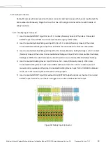
4.2.3
Control Box
Figure 28: The Exterior and Diagram of the Control Box
CAUTION:
The control box can be placed on the floor or in your working cell. Note that 5 cm
clearance should be left at both sides for ventilation.
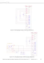
Use the M4L6 screw to secure the ground wire with the control box as shown below.


