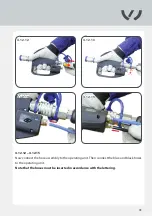
TKR Group VAS 6790/2 Скачать руководство пользователя страница 47

47

4.13.5

4.14.1

4.14.2

4.14.3

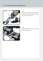
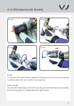
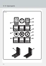
4.14  Maintenance and cleaning

4.14.1 – 4.14.3
Disconnect the blind riveting tool from the operating unit and/or the high-pressure coupling.  
Remove the high-pressure coupling from the Compact Booster.

4.13.5
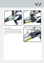
To close, press the mandrel collector towards the riveting tool, as shown in the laser engraving. 
Turn the mandrel collector to close the recovery aperture.

Содержание VAS 6790/2

Страница 1: ...ng tool Translation of original instruction manual ATTENTION This supplementary sheet serves as a supplement to the instruction manual BA1 VAS 6790 2 VAS 6792 VAS 6792 1 VAS 6792 2 and may only be used in conjunction with it Additional information to the instruction manual BA1 VAS 6790 2 VAS 6792 VAS 6792 1 VAS 6792 2 ...

Страница 2: ...information zur Betriebsanleitung BA1 VAS 6790 2 VAS 6792 VAS 6792 1 VAS 6792 2 ACHTUNG Diese Montageanleitung dient als Ergänzung zur Betriebsanleitung BA1 VAS 6790 2 VAS 6792 VAS 6792 1 VAS 6792 2 und darf nur im Zusammenhang mit dieser verwendet werden www tkr support com Owner s manual Owner s manual digital USB Stick 1 Download current owner s manuals 2 Support ...

Страница 3: ...se 4 1 Connecting the high pressure coupling to the Compact Booster 18 4 2 Connecting the blind riveting tool and the Compact Booster 20 4 3 VAS 6792 2 VAS 6792 24 Screwing the extension onto the blind riveting tool 22 4 4 Replacing the rivet head extension 27 4 5 Removing the extension 28 4 6 Replacing the conical grip 29 4 7 Connecting the spiral hose to the Compact Booster and hose adapter 32 4...

Страница 4: ...so applies to the extraction of individual illustrations and the use of text in the extract form 4 5 Use 4 9 Using the blind riveting tool 34 4 10 Replacing the rivet head 36 4 11 Fitting the ejector 37 4 12 Using with the operating unit 39 4 13 Emptying the mandrel collector 46 4 14 Maintenance and cleaning 47 4 15 Spare parts 50 4 16 Troubleshooting 54 Maintenance Service 5 1 Disposal BA1 60 5 2...

Страница 5: ...5 A C D B E 1 1 1 1 1 2 1 1 3 1 1 Designations Markings on the blind riveting tool A Manufacturer s identification B Serial number C Production date D Warnings for complete view see Fig 1 1 3 ...

Страница 6: ... BED 00000125 Vers 14 12 BA3 VAS 6792 11 Ø 2 0mm VAS 6792 13 Ø 3 0mm VAS 6792 12 Ø 4 0mm VAS 6792 14 Ø 2 6mm VAS 6792 10 Ø 3 4mm VAS 6792 27 Ø 4 0 4 2mm Ø 2 0mm Ø 2 6mm Ø 3 0mm Ø 3 4mm Ø 4 0mm Ø 4 0 4 2 mm Ø 4 0 4 2 mm Ø 3 4mm Ø 3 0mm Ø 2 6mm Ø 2 6mm Ø 2 6mm Ø 2 6mm VAS 6792 15 VAS 6792 17 VAS 6792 19 VAS 6792 16 VAS 6792 18 VAS 6792 20 L 2 1 Scope of Supply and Accessories ...

Страница 7: ...iveting tool C 1 Spiral hose assembly D 1 Ejector E 1 Compact Booster F 1 High pressure coupling G 1 Assembly wrench H 1 Assembly aid I 1 Hose adapter J 1 Blind rivet set K 1 Instruction manual L 1 Rivet matrix Accessories optional No Item M Extension 59 mm N Extension 160mm ...

Страница 8: ...6792 1 2 1 Scope of Supply and Accessories Accessories set optional No Item VAS 6792 1 O Extension 160 mm P Carrying strap Q Hose assembly R Operating unit S Plug connector T Pneumatic hose U Supporting belt V Cardboard box ...

Страница 9: ...ompact Booster The blind riveting tool is connected to the Compact Booster using a high pressure coupling Travel 20mm Setting force 24500 N at 6 bar Weight 0 8 kg without hose and operating unit Hydraulic operating pressure max 600 bar Pneumatic operating pressure 6 bar Ambient temperature 5 50 C 41 122 F Prescribed safety clothing Protective gloves eye protection long sleeved working clothes clos...

Страница 10: ...ation Clean compressed air Make sure that the pressure generator is only supplied with clean and dry compres sed air Moisture and contamination could cause equipment malfunction and or da mage Only use compressed air of quality class 2 as per ISO 8573 1 Always disconnect the riveter from the compressed air when leaving your workstation Warranty The manufacturer accepts no liability for damage or i...

Страница 11: ... conical grips All other necessary maintenance work and or repairs must be performed by the ma nufacturer or properly trained personnel only The user must only perform the maintenance and repair measures outlined in this instruction manual Maintenance and repair work not covered in this instruction manual may only be performed by professionals who have been correctly trained by TKR For further in ...

Страница 12: ...87 58 35 28 O 34 O 3 1 1 Overall length 179mm Length of mandrel collector 87mm Height 58mm Width 35 mm Ø Mandrel collector 34 mm Ø Rivet head 28 mm 3 1 Technical data Blind riveting tool with mandrel collector ...

Страница 13: ...13 109 17 28 58 35 28 O 3 1 2 Overall length 109mm Length of ejector 17 mm Width 35 mm Height 58 mm Ø Ejector 38mm Ø Rivet head 28mm Blind riveting tool with ejector ...

Страница 14: ...6792 24 3 1 3 3 1 Technical data VAS 6792 24 VAS 6792 2 Overall length 360 mm 260 2 mm Height 58 mm 58 mm Ø Rivet head 20 mm 20 mm Width 35 mm 35 mm Length of straight housing 160 mm 59 mm Length of mandrel collector 87 mm 87 mm Ø Mandrel collector 34 mm 34 mm Blind riveting tool with mandrel collector and extension ...

Страница 15: ...15 O58 104 125 27 2 O 3 1 4 Length 125mm Ø Coupling 58mm Ø Connection 27 mm High pressure coupling ...

Страница 16: ...16 1 2 7 3 5 9 8 4 6 3 2 1 Q O R S T U Q O R S T U Q O R S T U Q O R S T U Q O R S T U A B C D E G H I F A B C D E G H I F 10 11 12 13 14 16 17 19 20 21 22 23 Q S T U 18 15 3 2 Device components ...

Страница 17: ... Spiral hose 7 Compact Booster 8 Hose adapter 9 Blind rivet set 10 Protection cover 11 Protection cover 12 Extension rod 13 Rivet head 14 Extension casing 15 Mandrel collector 16 Conical grip 17 Ejector 18 Plug connector 19 Extension 160 mm 20 Hose package 21 Operating unit 22 Pneumatic hose 23 Supporting belt ...

Страница 18: ...18 4 1 1 4 1 2 4 1 3 4 1 Connect the high pressure coupling to the Compact Booster 4 1 1 4 1 3 Press the lever on the Compact Booster to turn the locking mechanism clockwise ...

Страница 19: ...19 4 1 4 4 1 5 4 1 6 4 1 7 4 1 4 4 1 7 Insert the high pressure coupling straight into the seating on the Compact Booster and turn the locking mechanism counterclockwise until it engages ...

Страница 20: ...20 4 2 1 4 2 2 4 2 Connecting the blind riveting tool and the Compact Booster 4 2 1 4 2 2 Remove the protective caps from the high pressure coupling and the blind riveting tool ...

Страница 21: ...21 4 2 3 4 2 4 4 2 5 4 2 3 4 2 5 Use the high pressure coupling to connect the blind riveting tool and the Compact Booster ensuring they engage audibly ...

Страница 22: ...VAS 6792 2 VAS 6792 24 Screwing the extension onto the blind riveting tool 4 3 1 Remove the mandrel collector from the blind riveting tool 4 3 2 4 3 3 Remove the conical grip from the blind rive ting tool The extension is set up as shown in Fig 4 3 3 ...

Страница 23: ...23 4 3 4 4 3 5 4 3 6 4 3 4 4 3 6 Unscrew the yellow protective cover from the extension Remove the extension sleeve from the housing Then remove the extensi on rod from the extension sleeve ...

Страница 24: ...AS6792 2 Before setting up al ways position the conical grip in the tool correctly using the assembly aid 4 3 7 4 3 8 Insert the appropriate conical grip into the extension rod 4 3 9 Then relocate the extension rod back into the extension sleeve 4 3 VAS 6792 2 VAS 6792 24 Screwing the extension onto the blind riveting tool ...

Страница 25: ...d riveting tool before fully securing the extension sleeve up to the stop with the assembly wrench Take extra care over this ensuring that the assembly wrench is positioned in the notches provided in the blind riveting tool to allow the extension sleeve to be detached ...

Страница 26: ...xtension casing over the extension sleeve and secure it to the blind riveting tool Hand tighten the casing with the assembly wrench Then fit the mandrel collector 4 3 VAS 6792 2 VAS 6792 24 Screwing the extension onto the blind riveting tool ...

Страница 27: ...27 4 4 1 4 4 2 4 4 Replacing the extension rivet head 4 4 1 4 4 2 When changing the rivet head on the extension note that it must be hand tightened using the assembly wrench ...

Страница 28: ...be removed 4 5 2 Then fit the assembly wrench to the blind riveting tool at the back Take particular care to ensure that the assembly wrench is posi tioned in the notches provided in the blind riveting tool to allow the extension sleeve to be detached Remove the conical grip from the extension sleeve and replace it in the blind riveting tool ...

Страница 29: ... 2 4 6 3 4 6 Replacing the conical grip 4 6 1 4 6 2 Unscrew the rivet head with the assembly wrench and remove 4 6 3 Position the conical grips at the point of the assembly aid Ensure that the conical side faces up ...

Страница 30: ... 2 0mm Ø 2 6mm Ø 3 0mm Ø 3 4mm Ø 4 0mm Ø 4 0 4 2 mm Ø 4 0 4 2 mm Ø 3 4mm Ø 3 0mm Ø 2 6mm Ø 2 6mm Ø 2 6mm Ø 2 6mm VAS 6792 15 VAS 6792 17 VAS 6792 19 VAS 6792 16 VAS 6792 18 VAS 6792 20 4 6 4 4 6 5 4 6 Replacing the conical grip 4 6 4 4 6 5 Insert the assembly aid into the opening in the blind riveting tool Select the right conical grip for the rivet head see rivet matrix ...

Страница 31: ...31 4 6 6 4 6 7 4 6 8 4 6 6 4 6 8 Once the conical grip has been inserted into the blind riveting tool the mandrel collector must be fitted ...

Страница 32: ...he spiral hose to the Compact Booster and hose adapter 4 7 3 4 7 4 Connect the plug on the hose to the hose adapter The hose adapter can now be connected up to the workshop s air supply 4 7 1 4 7 2 Connect the spiral hose to the Compact Booster ...

Страница 33: ... 3 4 8 1 4 8 3 Connect the spiral hose with the hose adapter and the black pneumatic hose Then secure the pneumatic hose to the Compact Booster 4 8 Connecting the pneumatic hose to the Compact Booster and the spiral hose ...

Страница 34: ... 4 9 4 4 9 Using the blind riveting tool 4 9 1 4 9 2 Insert the blind rivet centered in the tool s rivet guide 4 9 3 4 9 4 Position the blind riveting tool and insert it into the hole provided as far as the contact surface ...

Страница 35: ...n by pressing the lever on the Compact Booster Draw the mandrel into the tool The projecting part of the mandrel breaks at the front side at the intended breaking point This causes the rivet material to spread out around the rivet head on the opposite side ...

Страница 36: ...36 4 10 1 4 10 2 4 10 Replacing the rivet head 4 10 1 4 10 2 When changing the rivet head the replacement rivet head must be hand tightened with the assembly wrench ...

Страница 37: ...2 Turn the mandrel collector counterclockwise The compressed air supply MUST be switched off 4 11 Fitting the front ejector When opening the blind riveting tool hold it angled slightly forward because the conical grip can fall out ...

Страница 38: ...4 11 5 4 11 6 Tighten by hand using the large opening of the assembly wrench When not in use keep the front ejector in the protective cover provided for this purpose 4 11 3 4 11 4 Insert the front ejector and tighten clockwise until the contact surface is reached ...

Страница 39: ...39 4 12 1 4 12 2 4 12 3 4 12 Using with the operating unit 4 12 1 4 12 3 Remove the protective cap on the hose as sembly and connect the coupling to the high pressure coupling on the Compact Booster ...

Страница 40: ... Using with the operating unit 4 12 4 Lead the blue and black hoses through the opening in the locking mechanism so they are out of the way during use 4 12 5 Connect the blue hose to the hose assembly to the Compact Booster ...

Страница 41: ...41 4 12 6 4 12 7 4 12 8 4 12 6 4 12 8 Secure the support belt around the depres sed lever on the Compact Booster because rivet setting is controlled by the operating unit ...

Страница 42: ...the black hose to the plug connector Always ensure that the plug con nector symbol is pointing toward the black hose 4 12 10 Then connect the spiral hose to the other side of the plug connector 4 12 11 Remove the protective cap from the pressure connection on the operating unit ...

Страница 43: ... 13 4 12 14 4 12 15 4 12 12 4 12 15 Now connect the hose assembly to the operating unit Then connect the blue and black hoses to the operating unit Note that the hoses must be inserted in accordance with the lettering ...

Страница 44: ... 12 Using with the operating unit 4 12 16 Remove the front protective cap on the ope rating unit and the protective cap on the blind riveting tool 4 12 17 4 12 18 The blind riveting tool can now be connected to the operating unit ...

Страница 45: ...45 4 12 19 4 12 19 The blind riveting tool must be used as shown in the illustration by a professi onal operator trained in its use ...

Страница 46: ...nd riveting tool as shown in the laser engraving 4 13 2 4 13 4 Turn the mandrel collector to open the recovery aperture to allow the mandrels to be removed Empty the mandrel collector no more than 10 riveting operations If there are more than 10 mandrels in the collector this can result in damage to the riveting tool ...

Страница 47: ...ind riveting tool from the operating unit and or the high pressure coupling Remove the high pressure coupling from the Compact Booster 4 13 5 To close press the mandrel collector towards the riveting tool as shown in the laser engraving Turn the mandrel collector to close the recovery aperture ...

Страница 48: ...48 4 14 4 4 14 Maintenance and cleaning 4 14 4 Remove the conical grip from the housing If a cone is left behind the piston and the seal both the tool and cone will be damaged ...

Страница 49: ...grip Replace the conical grip if it is blunt Rounded teeth can cause faulty operation or damage to the tool Never use compressed air to clean the tool casing This will result in dirt being blown into the seals Use a soft lint free cloth to clean the tool ...

Страница 50: ...50 21 20 50 55 A1 B1 C1 D1 F1 I1 H1 L1 N1 R1 Q1 P1 M1 K1 J1 G1 E1 O1 4 15 1 4 15 Spare parts ...

Страница 51: ...ating unit G1 VAS 6792 23 Pneumatic hose black Ø 6 mm H1 VAS 6792 3 Blind riveting toolbox I1 VAS 6790 20 Compact Booster J1 VAS 6792 22 Plug connector K1 VAS 6790 54 Compact Booster hose adapter L1 VAS 6792 6 Assembly wrench M1 VAS 6792 5 Assembly aid N1 VAS 6792 4 Blind riveting tool O1 VAS 6792 24 Extension 160 mm P1 VAS 6792 2 Extension 59 mm Q1 VAS 6790 50 Empty folder A5 R1 VAS 6792 21 Front...

Страница 52: ...8 Ø 3 4 mm VAS 6792 16 Ø 2 6 mm VAS 6792 19 Ø 4 0 mm VAS 6792 15 Ø 2 0 mm VAS 6792 17 Ø 3 0 mm VAS 6792 20 Ø 4 0 4 2 mm Ø3 4 Ø2 Ø 2 6 Ø 3 0 Ø 4 0 Ø 4 2 4 15 2 A2 B2 C2 D2 F2 H2 I2 K2 M2 L2 J2 G2 E2 4 15 Spare parts ...

Страница 53: ...Conical grip welding mandrel E2 VAS 6792 16 Conical grip 2 6 mandrel F2 VAS 6792 13 Rivet holder for 3 0 mandrel G2 VAS 6792 18 Conical grip 3 4 mandrel H2 VAS 6792 11 Rivet head for 2 0 mandrel I2 VAS 6792 17 Conical grip 3 0 mandrel J2 VAS 6792 20 Conical grip 4 2 mandrel K2 VAS 6792 15 Conical grip 2 0 mandrel L2 VAS 6792 8 Blind rivet set box M2 VAS 6792 9 Blind rivet set ...

Страница 54: ...ck and blue hoses not connected Insufficient air pressure Hydraulic hose assembly not coupled Compact Booster defective Blind riveting tool cannot be switched off Control lines black and blue hoses incorrectly connected Control lines black and blue hoses not connected Control valve defective operating unit Compact Booster defective Air leak Control valve defective operating unit ...

Страница 55: ...ct hydraulic hose assembly in accordance with Operating Instructions 4 7 4 8 Arrange for repair by manufacturer service partner see BA1 Connect control lines black and blue hoses correctly ensuring they are properly seated 4 12 Connect control lines black and blue hoses correctly ensuring they are properly seated 4 12 Arrange for repair by manufacturer service partner 2 5 Arrange for repair by man...

Страница 56: ...separated from rivet head Insufficient quantity of oil pressure intensifier Gripper teeth on conical grips worn Compact Booster defective Insufficient air pressure Oil leak Hydraulic hose assembly defective High pressure coupling defective Blind riveting tool losing oil Screwing spring assembly ejector into housing requires application of excessive force Piston not in starting position quantity of...

Страница 57: ...repair by manufacturer service partner see BA1 Check air supply at pressure intensifier see BA1 Replace hydraulic hose assembly 2 5 Arrange for repair by manufacturer service partner 2 5 Arrange for repair by manufacturer service partner 2 5 Allow residual oil pressure to disperse by connecting the hydraulic hose and the high pressure push fit nipple wait 10 20 seconds 4 12 Check thread and replac...

Страница 58: ...ing Problem Cause Blind rivet cannot be inserted Conical grips in piston adapter 3 part sitting in different positions Mandrel collector overfilled broken off mandrels can no longer be carried back Incorrect conical grips ...

Страница 59: ...uide and gently push conical grips back 2 5 mm with a blunt implement until they are evenly positioned 4 6 Empty the collector Use a blunt implement to push back any mandrels left in the casing 4 13 Check and replace conical grips 4 6 ...

Страница 60: ...draulic oils and lubricants can be dangerous because they can contamina te groundwater Used oil must not be mixed with other waste materials and different types of used oil must not be mixed Pay particular attention to the terms of the German Environmental Liability Act and the Used Oil Directive including the stipulations they contain in regard to criminal acts and breaches of regulations The man...

Страница 61: ...ser customer provided that the tool is purchased from an au thorised sales outlet and is used as described in the instructions and for the purposes for which it was designed The warranty becomes invalid if the tool is used for purposes other than those for which it was designed In addition the warranty becomes invalid if the tool is not used as described in the instruc tion manual In the event of ...

Страница 62: ...d in accordance with the standards and guidelines listed below by TKR Spezialwerkzeuge GmbH Am Waldesrand 9 11 58285 Gevelsberg Germany Applied Product Safety Law ProdSG harmonised EN 693 EN 11148 1 EN 11148 10 EN 792 13 standards EN ISO 4413 EN ISO 4414 ISO 11200 ISO 11202 EN ISO 12100 Serial number range 00001 10000 EU Machine Directive 2006 42 EC As manufacturer we declare that The products mar...

Страница 63: ......

Страница 64: ...Am Waldesrand 9 11 D 58285 Gevelsberg Germany Phone 492332 66607 0 Fax 492332 66607 941 E mail info tkrgroup com Web www tkrgroup com PSD BED 00000158 Rev4 19 01 ...

Отзывы: