background image

User Manual - Network Dome Camera – 

&ϭϬϬϭsϭͲ/ͬd

3

Please take attention that changes or modification not expressly 
approved by the party responsible for compliance could void the 
user’s authority to operate the equipment. 

FCC compliance:

 This equipment has been tested and found to 

comply with the limits for a Class B digital device, pursuant to part 
15 of the FCC Rules. These limits are designed to provide reasonable 
protection against harmful interference in a residential installation. 
This equipment generates, uses and can radiate radio frequency 
energy and, if not installed and used in accordance with the 
instructions, may cause harmful interference to radio 
communications. However, there is no guarantee that interference 
will not occur in a particular installation. If this equipment does 
cause harmful interference to radio or television reception, which 
can be determined by turning the equipment off and on, the user is 
encouraged to try to correct the interference by one or more of the 
following measures: 

Reorient or relocate the receiving antenna. 

Increase the separation between the equipment and receiver. 

Connect the equipment into an outlet on a circuit different from 
that to which the receiver is connected. 

Consult the dealer or an experienced radio/TV technician for help. 

FCC Conditions 

This device complies with part 15 of the FCC Rules. Operation is 
subject to the following two conditions: 

1. This device may not cause harmful interference.

2. This device must accept any interference received, including
interference that may cause undesired operation.

Содержание FD1001V1-EI/T

Страница 1: ...USER MANUAL V2017 1 001 Network Dome Camera FD1001V1 EI T...

Страница 2: ...CT WITH INTERNET ACCESS THE USE OF PRODUCT SHALL BE WHOLLY AT YOUR OWN RISKS OUR COMPANY SHALL NOT TAKE ANY RESPONSIBILITES FOR ABNORMAL OPERATION PRIVACY LEAKAGE OR OTHER DAMAGES RESULTING FROM CYBER...

Страница 3: ...ere is no guarantee that interference will not occur in a particular installation If this equipment does cause harmful interference to radio or television reception which can be determined by turning...

Страница 4: ...of equivalent new equipment or dispose of it at designated collection points For more information see www recyclethis info 2006 66 EC battery directive This product contains a battery that cannot be...

Страница 5: ...strict compliance with the electrical safety regulations of the nation and region Please refer to technical specifications for detailed information Input voltage should meet both the SELV Safety Extra...

Страница 6: ...ot drop the camera or subject it to physical shock Do not touch sensor modules with fingers If cleaning is necessary use clean cloth with a bit of ethanol and wipe it gently If the camera will not be...

Страница 7: ...cording to their average enduring time The average time varies because of differences between operating environment and using history so regular checking is recommended for all the users Please contac...

Страница 8: ...ng Mounting 20 2 2 3 Mounting with Wall Mounting Bracket 24 2 2 4 Mounting with Pendant Mounting Bracket 27 2 2 5 Mounting with Gang Box 30 Image and Focus Adjusting 32 2 3 2 3 1 3 Axis Adjustment 33...

Страница 9: ...is series belong to two appearance types Type I has the lens that zoom and focus levels must be manually adjusted via zoom focus lever Type II has a motor driven lens that zoom and focus adjustment ca...

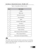
Страница 10: ...Dome Camera s d 10 Figure 1 1 Overview of Type I Camera Table 1 1 Description of Type I Camera No Description 1 Bubble 2 Black Liner 3 Lens 4 Mounting Base 5 Reset 6 Auxiliary Video Output 7 Serial P...

Страница 11: ...arm Interface z Press RESET about 10s when the camera is powering on or rebooting to restore the default settings including the user name password IP address and port No etc z Some of the models suppo...

Страница 12: ...User Manual Network Dome Camera s d 12 1 2 Type II Camera The overview of the Type II network dome camera is shown below 1 2 3 4 5 6 7 8 9 10 11 12 13 Overview of Type II Camera Figure 1 3...

Страница 13: ...set 6 Auxiliary Video Output 7 Serial Port 8 Memory Card Slot 9 Network Interface 10 Power Interface 11 Audio Input and Output Interface 12 Video Output Interface 13 Alarm Input and Output Interface P...

Страница 14: ...camera that supports IR you are required to pay attention to the following precautions to prevent IR reflection Dust or grease on the dome cover will cause IR reflection Please do not remove the dome...

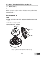
Страница 15: ...disassemble the camera and install the memory card first 2 1 1 Disassembling Steps 1 Loosen the three screws on the edge of the bubble with the screw driver 2 Lift and put aside the bubble 3 Remove th...

Страница 16: ...card slot 2 Insert the memory card into the memory card slot and push to get it mounted Memory Card Memory Card Slot Install the Memory Card Figure 2 2 3 Optional To unmount the memory card push to e...

Страница 17: ...ht Vandal proof Dome Camera Side Cable Outlet Figure 2 3 The Drill Template If you want to route the cables inside the ceiling drill a cable hole in the ceiling according to the drill template Route a...

Страница 18: ...the Camera 4 Adjust the surveillance angle zoom and focus level Refer to the Section 2 3 for detailed information 5 Install the inner black liner back to the camera 6 Install the bubble back to the c...

Страница 19: ...it for cable routing Steps 1 Rotate the water proof plug counterclockwise to remove it from the camera Water proof Plug Side Cable Outlet Figure 2 6 Remove the water proof plug 2 Route the cables thro...

Страница 20: ...g Mounting Before you start In ceiling mounting bracket is not included in package If you choose this mounting type you have to prepare a bracket first The in ceiling mounting bracket shown in below i...

Страница 21: ...Rim Main Body Cut a Hole for In ceiling Mounting Figure 2 9 2 Align No 1 screw holes with the corresponding screw holes on the bracket and secure the mounting base to the bracket with screws In ceili...

Страница 22: ...cure the camera to the mounting base In ceiling Mounting Bracket Camera Mounting Base Screw Holes for Camera Fixing Install the Camera to the Mounting Base Figure 2 11 4 Place the bracket and camera t...

Страница 23: ...screw them clockwise Toggle Bolts fix the bracket Fix the Bracket in Ceiling Figure 2 12 5 Adjust the surveillance angle refer to Section 2 3 6 Install the black liner and the bubble back to the camer...

Страница 24: ...racket Before you start Wall mounting bracket is not included in package If you choose this mounting type you have to prepare a bracket first The wall mounting bracket shown in below is only for demon...

Страница 25: ...e the cables install the wall mounting bracket and secure the cap on the bracket Wall Mounting Bracket Cap Install Wall Mounting Bracket Figure 2 16 2 Align the screw holes of the mounting base with t...

Страница 26: ...g Base Install the Mounting Base Figure 2 17 4 Align the camera with the mounting base and secure the camera with screws Secure the Camera Figure 2 18 5 Connect the video output connector to the monit...

Страница 27: ...ure Black Liner and Bubble Figure 2 19 2 2 4 Mounting with Pendant Mounting Bracket Before you start Pendant mounting bracket is not included in package If you choose this mounting type you have to pr...

Страница 28: ...2 20 Steps 1 Route the cables and Install the pendant mounting bracket Secure the cap on the bracket Pendant Mounting Bracket Cap Install the Pendant Mounting Bracket Figure 2 21 2 Align the screw ho...

Страница 29: ...l Network Dome Camera s d 29 3 Secure the mounting base to the cap with screws Cap Mounting Base Install the Mounting Base Figure 2 22 4 Align the camera with the mounting base and secure the camera w...

Страница 30: ...tion 2 3 for more detailed information 6 Install the inner black liner back to the camera 7 Secure the bubble to the camera with screws Secure Black Liner and Bubble Figure 2 24 2 2 5 Mounting with Ga...

Страница 31: ...31 Gang Box Mounting Base Figure 2 25 Install the Mounting Base 3 Route the cables through the hole in the center of the mounting base 4 Align the camera with the mounting base And secure the camera w...

Страница 32: ...detailed information 6 Install the inner black liner back to the camera 7 Secure the bubble to the camera with screws Figure 2 27 Secure the Black Liner and Bubble Image and Focus Adjusting 2 3 Before...

Страница 33: ...uxiliary video cable is not included in the package Instead you can connect the video out interface of the camera to a monitor for image and focus adjustment Video Out Interface Video Out Interface of...

Страница 34: ...le of the image Pan 0 to 355 Rotate 0 to 355 Tilt 0 to 90 3 axis Adjustment Figure 2 30 2 3 2 Zoom and Focus Adjustment Type I For Type I camera you can use zoom lever and focus lever to adjust the le...

Страница 35: ...ver between F Far and N Near to obtain the optimum focus 5 Tighten the focus lever Type II Type II camera is equipped with a motor driven lens You can adjust the zoom and focus level on PTZ control pa...

Страница 36: ...s and information leakage please strengthen your own protection If the product does not work properly please contact with your dealer or the nearest service center 3 1 Wiring Please connect to the cam...

Страница 37: ...ples to introduce the camera activation Please refer to the User Manual of Network Camera for Activation via Client Software 3 2 1 Activation via Web Browser Steps 1 Power on the camera and connect th...

Страница 38: ...assword monthly or weekly can better protect your product 4 Confirm the password 5 Click OK to save the password and enter the live view interface 3 2 2 Activation via TKHSDM Software TKHSDM software...

Страница 39: ...RECOMMENDED We highly recommend you create a strong password of your own choosing using a minimum of 8 characters including upper case letters lower case letters numbers and special characters in orde...

Страница 40: ...in the same subnet with your PC Then install the TKHSDM software or client software to search and change the IP of network camera We will take modifying the IP Address via TKHSDM software as an exampl...

Страница 41: ...User Manual Network Dome Camera s d 41 Figure 3 5 Modify the IP Address 4 Input the password to activate your IP address modification The batch IP address modification is supported by the TKHSDM...

Страница 42: ...Open the web browser 2 In the browser address bar input the IP address of the network camera and press the Enter key to enter the login interface Note z The default IP address is 192 168 1 64 z If th...

Страница 43: ...ing the live video and managing the camera Please follow the installation prompts to install the plug in Note You may have to close the web browser to finish the installation of the plug in Figure 4 2...

Страница 44: ...User Manual Network Dome Camera s d 44 Note For detailed instructions of further configuration please refer to the user manual of network camera...

Страница 45: ...Zuidelijk Halfrond 4 P O Box 415 2801 DD Gouda 2800 AK Gouda The Netherlands www tkhsecurity com...

Отзывы: