Titon CME1 Скачать руководство пользователя страница 1

ventilation systems

Product Manual

Titon CME1

Mechanical Extract Ventilation Unit

Online Version

Содержание CME1

Страница 1: ...ventilation systems Product Manual Titon CME1 Mechanical Extract Ventilation Unit Online Version ...

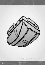
Страница 2: ...2 PCT Patent Application No PCT GB2009 000114 Online Version ...

Страница 3: ... Installation Safety and Guidance 8 Transportation Packaging Storage 9 Inspection 9 Parts List 9 Preparation 9 Dimensions 10 Component Identification 11 Fixing 12 Ducting Best Practice 14 Ducting Connection 15 Wiring 18 Commissioning Speed Setting 20 How to Change Speeds 21 Maintenance Cleaning 22 Declaration of Conformity 25 Service Record 26 3 Contents Online Version ...

Страница 4: ...l for the good health of your home and its occupants How your Titon CME1 system works How to operate and maintain your Titon CME1 For the professional installer this Product Manual explains How to install the Titon CME1 How to commission the unit How to maintain the unit It is important to read this Product Manual to ensure your ventilation system is installed commissioned and used properly and co...

Страница 5: ...y reduced air leaks and indoor air quality can deterio rate rapidly without the use of products made to control ventilation Chemicals gases and moisture produced by every day products and activities may lead to the build up of excessive levels of pol lutants which are harmful to the health of the occupants and may damage the building Poor ventilation can be a major contributory factor of heart dis...

Страница 6: ...ze and style of the home Most systems will also have a facility to boost the extraction rate at times when more moisture is being generated such as when bathing or cooking This may be done automatically by electronic sensors or by a conveniently located boost switch for manual operation DONOTswitchofftheunit itisdesignedtoruncontinuously Iftheunitisswitched off indoor pollutant and moisture levels...

Страница 7: ... and pollut ants which boost the system automatically All ventilation units require periodic maintenance and this must only be carried out by a suitably qualified and competent person See the servicing and maintenance section for further details Product Features Boost Control normally via a two way switch Compact low profile unit Hidden installation fixings All duct ports on one level Accepts 204m...

Страница 8: ...ated away from any flue outlet in accordance with relevant Building Regulations Always ensure ducting is free from blockages before switching the unit on We recommend a minimum distance of 200mm between the appliance and any sharp bends in duct work Installation of the appliance MUST be carried out by a qualified and suitably competent person and should be carried out in clean dry conditions where...

Страница 9: ...1 CME1 Screw Pack x 1 All shortages or damage must be reported to the supplier Preparation Important read these instructions fully before the installation of this appliance NEVER install the CME1 in an area which does not have sufficient access the for future maintenance see Dimensions or box in the unit as the area may subse quently surface finished making access to the unit difficult NEVER insta...

Страница 10: ...gram shows the overall dimensions of the unit and the additional space required around the unit once installed to allow for future servicing and maintenance 450 421 355 390 252 550 450 590 Service Void All dimensions in mm Online Version ...

Страница 11: ...11 Installation Component Identification CME1 Unit components Cover Inlet ring Base Scroll Base Cover Scroll Inlet Ring assembly Online Version ...

Страница 12: ...screws Always use a fixing type and length suited to the substrate type The unit weighs approximately 5kg Mount the BASE ensuring it is not distorted by the fixings or mounting surface Clip the MOTOR and LID assembly to the BASE ensure that all 6 clips have engaged Do not use power tools to tighten screws Tighten screws by hand Do not over tighten screws 1 2 3 4 5 1 2 3 4 5 6 260 260 EXTRACT PORT ...

Страница 13: ...ain the screws 1 Fit two screws through the pre formed holes at the front of the INLET RING to securely fix the INLET RING SCROLL assembly to the BASE 2 Fit one screw through the preformed hole in the back of the BASE to securely fix the INLET RING SCROLL assembly to the BASE 3 Online Version ...

Страница 14: ... is minimised We recommend a minimum distance of 200mm between the appliance and any sharp bends in duct work Ducting terminal for Exhaust must be to the external air outside the building envelope Ducting in unheated spaces must always be insulated to prevent condensation forming within the ducting Additional guidance can be found in the Residential Ventilation Associa tion Installation Good Pract...

Страница 15: ...ng fits inside the ports To enable fitment of 110x54mm ducting modify the convertible port cover by tearing out the rip strip When using the convertible port cover ensure the tear out section is completely removed Installation Online Version ...

Страница 16: ...ides using a suitable ducting tape and or silicone type sealant Unused extract ports must be fitted with non converted or undamaged port covers Ducting Connection 110mm x 54mm ducting fits inside the convertible port cover Installation Online Version ...

Страница 17: ...17 Installation Notes Online Version ...

Страница 18: ...e to the fixed wiring A boost switch must be connected for the unit to run see wiring diagram a con nection is required between COM and L1 or L2 for the unit to operate Boost controls must not be located in a bath shower room or within 1 metre of a cooker or where they may be affected by excessive heat or moisture Boost controls should be clearly identified and conveniently located The boost can b...

Страница 19: ...19 Installation Wiring Internal Cable Routing Cable Access Two Way switch Double Pole Isolator 3A Fuse L N L2 L1 L COM N Wiring Diagram for Continuous Speed 1 2 or 3 and Boost Speed 4 Online Version ...

Страница 20: ...tions 0 50 150 200 250 300 350 400 450 100 Air Flow l s Resistance Pa 0 20 40 60 80 100 120 140 Fan Curve Speed 1 2 3 4 Volts 90 125 160 230 Curve Speed Table Transformer Connections BLUE BROWN BLACK Boost GREY Continuous 90 125 160 L N Online Version ...

Страница 21: ...ion rates appropriate to the dwelling requirements If adjustment is required follow the steps below Isolate the appliance from the mains power supply Remove the cover from the unit the unit Reposition the crimped connectors on the transformer to select an alternative continuous or boost speed settings GREY wire continuous rate BLACK wire boost rate Do not reposition the BLUE or BROWN wire Refit th...

Страница 22: ...a 230V supply and contains rotating mechanical parts Isolate the unit from mains power supply and allow sufficient time for all moving parts to stop before undergoing any Servicing or Maintenance To gain access to the interior of the unit for cleaning Unscrew the 3 retaining screws that hold on the COVER and remove Maintenance Remove the 4 SCROLL retaining screws 3 3 1 1 2 2 4 4 Online Version ...

Страница 23: ...eaning Using a flat bladed screw driver un clip SCROLL from INLET RING by disengaging the 3 retaining clips Ensure that the SCROLL is supported and does not strain the cables Remove the 3 retaining screws Online Version ...

Страница 24: ...ceding instructions Ensure all fasteners are secure before returning power to the unit Do not use power tools to tighten screws Tighten screws by hand Do not over tighten screws After servicing always complete the service record Cleaning Using a flat bladed screwdriver un clip the INLET RING from BASE by disengaging the 4 retaining clips Title 2 1 4 3 1 2 Online Version ...

Страница 25: ...EC LVD 2004 108 EC EMC Applied Harmonised Standards EN 60335 1 2002 A2 2006 EN 60335 2 80 2003 AI 2004 Manufacturer Titon Hardware Limited Signature of manufacturer representatives N C Howlett Development and Sustainability Director P S Cowell Research and Testing Manager BEng Hons CEng MCIBSE R Brighton Managing Director Manufacturing Division International House Peartree Road Stanway Colchester ...

Страница 26: ...Serviced by Company name Date Notes Service Record 26 Online Version ...

Страница 27: ...Service Record Serviced by Company name Date Notes 27 Online Version ...

Страница 28: ...on system is complete This Product Manual must be kept in the Home Information Pack and used as a service record Installed by MARKETING DIVISION International House Peartree Road Stanway Colchester Essex CO3 0JL Tel 44 0 1206 713800 Fax 44 0 1206 543126 Email ventsystems titon co uk Web www titon com Online Version ...

Отзывы: