background image

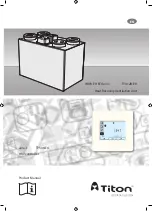
Product Manual

ventilation systems

EN

HRV controller

aura-t


TP536/EU

Heat Recovery Ventilation Unit


HRV3 PH ECO

aura


TP412B PH

Содержание aura-t TP536/EU

Страница 1: ...Product Manual ventilation systems EN HRV controller aura t TP536 EU Heat Recovery Ventilation Unit HRV3 PH ECOaura TP412B PH ...

Страница 2: ...communication cables should not be placed within 50mm or on the same metal cable tray as any 230V lighting or power cables 12 Ensure all cable glands are fully tightened and supplied grommets are used 13 The unit must be stored in a clean and dry environment Do not install the appliance in areas where the following may be present or occur Excessive oil or a grease laden atmosphere Corrosive or fla...

Страница 3: ...ove roof level the section above the roof should be insulated or a condensate trap should be fitted just below roof level 3 Ducts within the building heated envelope between the external terminals and the unit s From Atmosphere and To Atmosphere ports should be insulated and wrapped additionally with a vapour barrier outside the insulation 4 Where ducts pass through fire barriers they must be appr...

Страница 4: ...st Protection Program 7 Shut Down of Supply Fan 7 3 xVolt Free Inputs 7 2 x Live Switch Inputs 7 2 x Proportional Sensor Inputs 7 Dimensions 8 HRV3 8 aura t 8 Installation HRV3 9 Condensate Drain 10 Ducting Connections 11 Wiring Connections Access 11 aura t 12 Location 12 Fixing 12 aura t Wiring Diagrams 14 HRV3 Wiring Diagrams 15 Supply 15 Switching Controls 16 External Sensors 18 Duct Heater 22 ...

Страница 5: ...ays the status of a Titon ECOaura HRV unit It allows the unit to be commissioned and gives the user both manual and timed control of fan speeds The aura t is connected to the HRV via a low voltage connection and can be sited remotely from the unit Packaging Contents Inspect the unit when taking delivery Check the unit for damage and that all accessories have been supplied Package supplied with HRV...

Страница 6: ...onitored Internal Humidity Sensor The HRV has a relative humidity RH sensor The RH sensor can be programmed to switch the HRV into Boost Speed Boost Overrun Timer A programmable timer that controls the time the HRV remains at Boost Speed after all boost switches have been released Boost Delay Timer A programmable timer which can be used to delay the HRV running at Boost Speed after a boost switch ...

Страница 7: ... when a problem with the exhaust fan or associated ductwork causes insufficient warm air to be available to heat the incoming air supplied to the property The sensor monitoring the Supply Air into the property will stop both fan motors when this temperature measures below 5 C The Frost program icon will flash and the fan speeds will display 0 The unit will remain off until the fan key is pressed o...

Страница 8: ...Dimensions HRV3 DO NOT BOX IN UNIT aura t 23 70 87 87 aura t 426 Service Void Service Void 715 860 490 300 100 295 600 600 430 300 100 8 ...

Страница 9: ...a spirit level This line will be approximately 95mm below the location of the top face of the unit when fitted excluding duct ports 2 Use one of the Mounting Brackets as a template to mark the three fixing hole centres 3 Drill holes for fixings always use a fixing suited to the wall type 4 Fix one Mounting Bracket to the wall ensuring the interlocking side is at the top as shown 5 Fix the remainin...

Страница 10: ...ap which must act as an air lock Must be adequate secured and be insulated with the equivalent of at least 25mm of insulating material with a thermal conductivity of 0 04 W mK if any part of the pipe passes though an unheated void Should be installed to have a minimum 5 fall from the unit Titon recommend the use of diaphragm type waste valve in place of a conventional wet trap which could dry out ...

Страница 11: ...nnected to the ducting that carries the fresh warmed air to the habitable rooms from the HRV unit FROM ATMOSPHERE This duct port is connected to the ducting that carries fresh outdoor air to the HRV unit Wiring Connections Access All wiring must conform to current I E E Wiring Regulations and all applicable national standards and Building Regulations Read and observe the Warnings Safety Informatio...

Страница 12: ...ol cable will reach Fixing 1 Un clip the front of the aura t case from the Back Plate 2 Thread the control cable through the hole in the Back Plate 3 Fix Back Plate 4 Connect the communication cable see Wiring section 5 Clip the front of aura t to the Back Plate Connection to HRV 60 Fixing Holes Wiring Access Hole 12 ...

Страница 13: ...13 ...

Страница 14: ...ontrol cable may be supplied fitted with a plug in connector for connection to the HRV if the HRV does not have a socket remove the plug and use the wiring diagrams below 12V A B 0V HRV 12V A B 0V Connection to HRV Connection to aura t 14 ...

Страница 15: ...HRV3 Wiring Diagrams Supply Supply wiring Ref EE167 230V 2 Pole Isolator Fuse 15 ...

Страница 16: ... s must be supplied via the same circuit as used to power the unit A 3 LS1 only or 4 LS1 LS2 pole local isolator must be installed The Boxed Relay Part No TP505 may be required to switch from other circuits Wet Room Light Switch Kitchen Light Switch 230V 4 Pole Isolator 2 Pole Isolator Fuse 16 ...

Страница 17: ... Free Kitchen Boost SW2 Volt Free Wet Room Boost SW3 Volt Free SUMMERboost Control Switch Defaults LS1 230V Kitchen Boost LS2 230V Wet Room Boost The Switched Live LS1 LS2 Boost s must be supplied via the same circuit as used to power the unit SW Live from Kitchen SW Live from Wet Room 17 ...

Страница 18: ...ng room thermostat TP509 Room Thermostat Volt free activation of Summer Mode using room thermostat TP509 Room Thermostat Volt free boost switching of MVHR using single pole switches TP502 TP503 TP507 and or TP500 TP501 Humidistat There is a maximum of 10 single pole switches or Humidistats that can be used TP506 Latching Summer Mode switch TP522 Latching SUMMERboost switch 1 2 3 T L Y1 Y2 T L Y1 Y...

Страница 19: ...Sensor Additional Options TP540 RSQ Room Air Quality Sensor TP543 RST Room Temperature Sensor VOut 24Vdc Combined sensor load must not exceed 4W 3 Way rotary switch Ref EE162 Switch Positions TP508 Three Position Rotary Switch 1 Setback Speed 2 Continuous Speed 3 Boost Speed For this configuration to function correctly S1 1 Needs to be set to a Kitchen or Wet Room Boost switch S1 2 Needs to be set...

Страница 20: ...20 ...

Страница 21: ...21 ...

Страница 22: ...the EPP of the HRV unit in the position shown on the diagram 2 The sensor is secured to the ducting with two Ø3 0mm self tapping screws must be suitable for the ducting material using the two holes in the flange on the sensor 3 Apply a suitable sealant around the outside diameter of the flange to seal around the duct 4 The sensor position may need adjustment to ensure that the temperature of the a...

Страница 23: ...the TJK10K sensor positioned as shown the duct heater set point must be set to 6 C using the potentiometer on the front electrical cover of the duct heater Wiring To Duct Sensor 230V 2 Pole Isolator 5A Fuse N L 7 8 Duct Heater 23 ...

Страница 24: ...Summer Bypass Passcode settings Filter Reset Switch Setup in a Sub Menu If passcode is enabled enter 3333 to activate the above menus Run Mode The aura t controls the HRV unit s 4 programmable speed settings This is the Run Mode screen use the number buttons to select the required fan speed Press and Hold the 1 button to turn the unit off just the 1 icon will be displayed Tap the button to turn th...

Страница 25: ...iated ductwork causes insufficient warm air to be available to heat the incoming air supplied to the property The sensor monitoring the Supply Air into the property will stop both fan motors when this temperature measures below 5 C Summer Bypass is in operation air from outside is being supplied directly to the property without recovering heat from the Heat Cell This is often accompanied by SUMMER...

Страница 26: ... active and will be used to switch the HRV in and out of Speed 1 The Pause and Hour Glass symbols indicate the Timer is temporarily paused Timer will restart 8 hours after being invoked The Pause symbol indicates the timer is currently inactive and will have no effect on fan speeds this pause is indefinite Timer Setup Tap this button to adjust the Timer see Timer Setup section Tap this to Exit and...

Страница 27: ...ghted the HRV will run at the selected speed Extract Supply 2 Use the Supply to dwelling or Extract from dwelling buttons at the top of the screen to select which fan is to be adjusted 3 Use the arrow keys to adjust the fan speed The fan will respond in real time to the adjustment being made 4 Repeat the above for all fan speeds requiring adjustment 5 When all of the fan speeds are correct tap the...

Страница 28: ...ve the settings these will set the unit to run at Speed 1 between 08 00 12 00 1 Tap the event number to be edited 1 4 from on left hand side of the screen The selected event will highlight 2 Use the fan keys to select either the time the HRV will switch into Speed 1 or Speed 2 3 Speed 1 key toggles between selecting Speed 1 and selecting Speed 1 with Boost Inhibit indicated by Padlock Icon 4 The s...

Страница 29: ...days and the Enter key to select deselect 5 When all required day s have been selected tap the Save key to complete the copy and return to step 1 Day Selection Screen 6 Repeat day event and timer setup or tap the Exit key to return to Run Mode Timer Defaults Event timings The Speed 2 cannot be set earlier than Speed 1 Events where Speed 1 and Speed 2 are identical are ignored by the timer Days Eve...

Страница 30: ...e Setting Editing Arrow keys are used to change setting value Tapping the Enter key whist editing will save and move to the next setting in the list The order in which editable settings are displayed is as follows 1 Time 24 hour clock 2 Day of week 3 Humidity threshold 4 Kitchen Overrun timer 5 Wet room Overrun timer 6 Summer Bypass Setup 7 Passcode Disable Enable 8 Filter Reset If a filter change...

Страница 31: ... adjusted Supply represents from atmosphere air temperature Extract represents from dwelling air temperature Tap button 4 to enable disable SUMMERboost Unfilled icon shown represents disabled Passcode Enable Disable Tap Enter key to edit state Use to enable disable Passcode indicates Passcode is disabled 3 3 3 3 indicates Passcode is enabled 31 ...

Страница 32: ...Exit Key Press and Hold the Setup Mode tab to enter the Switch Setup Mode menu Switch Setup menu active All switch inputs to the HRV unit S1 S2 S3 LS1 LS2 can be assigned any of the following functions Kitchen Boost Speed 3 Wet Room Boost Speed 3 Speed 1 Setback SUMMERboost disable Speed 4 If Passcode is enabled acesss to the Switch Setup Menu is only avaiable from the Time setup menu 32 ...

Страница 33: ...33 ...

Страница 34: ...ol Front Cover Removal 1 ISOLATE the unit from mains power supply and allow sufficient time for all moving parts to stop 2 Loosen the two corner screws located on the bottom front of the unit 3 Completely remove the centre screw 4 Completely remove the Front Cover by pulling it away from the unit at the bottom and lifting Cover replacement is the reverse of the above steps Ensure it is securely lo...

Страница 35: ...elow The Unit part number can be found on the serial number label fixed to the top and front of the unit Model Part Number Filter Set HRV3 PHB ECOaura TP412B PH XP46232 099 How to Change Filters 1 Remove Front Cover 2 Slide out Filters 3 HRV3 PHB model use unequal Filters Make a note of which side of the unit the filters are fitted The position of the filters is marked on the unit G4 Filter Extrac...

Страница 36: ...ost Supply 14 100 70 Extract 14 100 70 Speed 4 SUMMERboost Supply 14 100 100 Extract 14 100 100 Summer Bypass Extract 17 C 35 C 25 C Supply 10 C 20 C 18 C In order for the Summer Bypass to operate the temperatures of both the air being extracted from the property and supplied from outside must be above their individual thresholds If the temperature of the Supply air is less than 1 C cooler than th...

Страница 37: ...Frost Protection threshold When operating in User Mode it uses the sensor on the from atmosphere side of the heat cell and the threshold and hysteresis detailed above In both modes the Duct Heater will be switched off if the Supply fan speed drops below 22 5 PWM Internal Humidity Boost On RH Boost Overrun 1 min 60 mins 15 mins RH Boost Hysteresis 1 10 1 When the Humidity of the air being extracted...

Страница 38: ...Service Record Serviced By Company Date Notes 38 ...

Страница 39: ...Serviced By Company Date Notes 39 ...

Страница 40: ...l ventsales titon co uk Web www titon com 2018 TITON DO 5607 Iss 02 In the event of any queries please contact the system installer Ensure this booklet is passed to the householder once installation commissioning of the ventilation system is complete This Product Manual must be kept in the Home Information Pack and used as a service record ...

Отзывы: