Titan RentSpray 400 Скачать руководство пользователя страница 4


 © Titan Tool Inc.  All rights reserved. 

Table of contents

Safety Precautions ................................................................... 2

Specifications ........................................................................... 3

General Description ................................................................. 4

Operation ................................................................................... 4


Setup ................................................................................... 4


Preparing to Paint................................................................ 4


Painting ............................................................................... 5


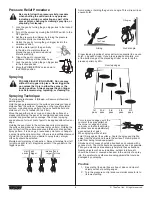
Pressure Relief Procedure .................................................. 6

Spraying .................................................................................... 6


Spraying Technique ............................................................ 6


Practice ............................................................................... 6

cleanup ..................................................................................... 7


Cleaning the Spray Tip ........................................................ 7

Maintenance .............................................................................. 7


General Repair and Service Notes...................................... 7


Replacing the PRIME/SPRAY Valve ................................... 8


Replacing the Filters............................................................ 8


Replacing the Motor Assembly............................................ 8


Replacing the Motor Brushes .............................................. 9


Replacing the Gears............................................................ 9


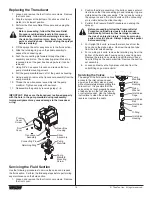
Replacing the Transducer ................................................. 10


Servicing the Fluid Section ................................................ 10

Troubleshooting ..................................................................... 12

Parts List ................................................................................. 18


Main Assembly .................................................................. 18


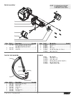
Motor Assembly................................................................. 19


Suction Set Assembly ....................................................... 19


Labels ................................................................................ 19


Gear Box Assembly........................................................... 20


Stand Assembly ................................................................ 21


Fluid Section Assembly ..................................................... 22


Electrical Schematic .......................................................... 23


Accessories ....................................................................... 24

Limited Warranty .................................................................... 28
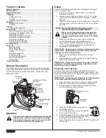
General Description

This airless sprayer is a precision power tool used for spraying 

many types of materials.  Read and follow this Owner’s Manual 

carefully for proper operating instructions, maintenance, and 

safety information.

Pressure Control 

Knob

ON/OFF 

Switch

PRIME/SPRAY 

Valve

Outlet Fitting

Circuit 

Breaker

Oil Cup

Siphon 

Tube

Return 

Hose

Filter

Operation

This equipment produces a fluid stream at extremely 

high pressure.  Read and understand the warnings 

in the Safety Precautions section at the front of this 

manual before operating this equipment.

Setup

Perform the following procedure before plugging in the power 

cord of an electric unit.

  1.  Ensure that the siphon tube and the return hose are 

attached and secure.

  2.  Using a wrench, attach a minimum of 50’ of 1/4” airless 

spray hose to the outlet fitting on the sprayer.  Tighten 

securely.

  3.  Attach an airless spray gun to the spray hose.  Using two 

wrenches (one on the gun and one on the hose), tighten 

securely.

 NOTE:  Do not attach the tip to the spray gun yet.  

Remove the tip if it is already attached.

Make sure all airless hoses and spray guns are 

electrically grounded and rated at or above the 

maximum operating pressure range of the airless 

sprayer. 

  4.  Make sure the pressure control knob is turned fully 

counterclockwise to its lowest pressure setting.

  5.  Make sure the ON/OFF switch is in its OFF position.

  6.  Fill the oil cup with approximately one tablespoon of 

separating oil (P/N 0279920).

IMPORTaNT:  Never operate unit for more than ten seconds 

without fluid.  Operating this unit without fluid will cause 

unnecessary wear to the packings.

  7.  Make sure the electrical service is 120V, 15 amp 

minimum.

  8.  Plug the power cord into a properly grounded outlet at 

least 25’ from the spray area.

IMPORTaNT:  always use a minimum 12 gauge, three-wire 

extension cord with a grounded plug.  Never remove the 

third prong or use an adapter.

Preparing a New Sprayer

If this sprayer is new, it is shipped with test fluid in the fluid 

section to prevent corrosion during shipment and storage.  This 

fluid must be cleaned out of the system thoroughly with mineral 

spirits before spraying paint.

IMPORTaNT:  always keep the trigger lock on the spray gun 

in the locked position while preparing the system.

  1.  Place the siphon tube into a container of mineral spirits.

  2.  Place the return hose into a metal waste container.

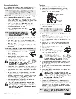
  3.  Set the pressure to minimum by turning the pressure 

control knob fully counterclockwise.

Pressure Control 

Knob

ON/OFF 

Switch


  4.  Move the PRIME/SPRAY valve down to 

the PRIME position.

  5.  Turn on the sprayer by moving the ON/OFF 

switch to the ON position.

  6.  Allow the sprayer to run for 15–30 seconds 

to flush the test fluid out through the return 

hose and into the waste container.

  7.  Turn off the sprayer by moving the ON/OFF switch to the 

OFF position.

Содержание RentSpray 400

Страница 1: ...ent before reading this manual RentSpray 400 Airless Sprayer Model Number 0552053 0711 Titan Tool Inc All Rights Reserved Form No 0552838D NOTE This manual contains important warnings and instructions...

Страница 2: ...injury as soon as possible DO NOT delay treatment to research toxicity Toxicity is a concern with some coatings injected directly into the blood stream Consultation with a plastic surgeon or reconstr...

Страница 3: ...doing Do not operate the unit when fatigued or under the influence of drugs or alcohol For electric units Always unplug cord from outlet before working on equipment Do not use the hose as a strength...

Страница 4: ...he gun and one on the hose tighten securely NOTE Do not attach the tip to the spray gun yet Remove the tip if it is already attached Make sure all airless hoses and spray guns are electrically grounde...

Страница 5: ...solvent to paint Be sure to follow the pressure relief procedure when shutting down the sprayer for any purpose including servicing or adjusting any part of the spray system changing or cleaning spra...

Страница 6: ...the gun closer to the surface deposits more paint on the surface and produces a narrower spray pattern Holding the gun farther from the surface produces a thinner coat and wider spray pattern If runs...

Страница 7: ...ing the ON OFF switch to the OFF position 10 Move the PRIME SPRAY valve up to its SPRAY position 11 Turn on the sprayer Ground the gun by holding it against the edge of the metal container while flush...

Страница 8: ...e gun head 6 Slide the handle over the handle tube and reattach it to the gun head 7 Secure the trigger guard back in position on the bottom of the handle NOTE For more detail part number information...

Страница 9: ...hroud with the two fan shroud screws 9 Slide the motor cover over the motor Secure the motor cover with the four motor cover screws Replacing the Gears 1 Perform the Pressure Relief Procedure and unpl...

Страница 10: ...edures to service the valves and repack the fluid section Perform the following steps before performing any maintenance on the fluid section 1 Loosen and remove the four front cover screws Remove the...

Страница 11: ...wer packings Refer to the illustration below for proper packing orientation Install lower packings with raised lip and O ring facing up Install upper packing with raised lip and O ring facing down O R...

Страница 12: ...set connection and tighten or re tape the connection with tape 3 Remove the pump filter element and clean Remove the inlet screen and clean 4 Remove the siphon tube suction set and clean 1 Replace the...

Страница 13: ...Titan Tool Inc All rights reserved 13 Notes...

Страница 14: ...n ou un sp cialiste en chirurgie reconstructive de la main DANGER MANATIONS DANGEREUSES Certains produits peintures solvants insecticides ou autres peuvent tre nocifs s ils sont inhal s ou entrent en...

Страница 15: ...grands vents Porter des v tements aptes prot ger la peau et les cheveux du produit utilis Ne pas utiliser le pistolet ou ne pas pulv riser de produits en pr sence d enfants proximit loigner les enfant...

Страница 16: ...os revestimientos inyectados directamente en la corriente sangu nea Puede ser aconsejable consultar con un cirujano pl stico o un cirujano especialista en reconstrucci n de las manos PELIGRO VAPORES P...

Страница 17: ...en todo momento No se asome ni se pare sobre soportes inestables Mantenga siempre la posici n firme y el equilibrio efectivos Use la presi n m s baja posible para enjuagar el equipo Mant ngase alerta...

Страница 18: ...cart only 2 9 0507783 Hose clip upright cart only 1 10 0508552 Siphon tube upright cart only 1 11 0551556 Return hose upright cart only 1 12 5006536 Inlet screen upright cart only 1 Item Part Descrip...

Страница 19: ...9 Return hose 1 3 0279459 Hose clip 1 4 0295565 Inlet screen 1 5 9871105 O ring 2 6 9822526 Retaining ring 1 7 9850638 Tie wrap 2 Labels Part Description 0552834 Logo label front 0552836 Logo label si...

Страница 20: ...Tool Inc All rights reserved Gear Box Assembly 1 2 3 4 5 9 10 11 12 13 14 15 16 17 18 6 7 8 19 18 20 21 22 23 25 24 26 27 28 NOTE All electrical work should be performed by a Titan authorized service...

Страница 21: ...0 Ground screw 1 17 0551112 Transducer assembly includes o ring 1 18 0551515 Circuit breaker 1 19 9850936 ON OFF switch 1 20 03662 Microswitch insulator 1 21 0295490 Microswitch 1 22 9800604 Screw 2 2...

Страница 22: ...nlet valve ball 1 18 0551534 Inlet valve seat 1 19 0509582 O ring 1 20 0508680 Inlet valve housing stand and low boy cart 1 0508690 Inlet valve housing upright cart 21 0551532 Filter assembly includes...

Страница 23: ...elay Capacitor Motor WHITE BLACK BLACK BLACK RED RED 90 Female Quick Connect Male Female Piggyback Female Quick Connect P N 0551496 P N 0551497 P N 0507974 P N 0551498 P N 0508650 P N 0295418 P N 0507...

Страница 24: ...71 Lubriplate contenant d environ 400 g 14 oz 314 172 Lubriplate contenant d environ 3 kg 6 lb 0521010 Paint Renew starter kit 0521523 Paint Renew 1 gallon de recharge 0297055 Bouclier de pompe Pump S...

Страница 25: ...malla 60 Las amplitudes de abanico entre 8 y 12 pulgadas 20 a 30 cm son preferibles porque ofrecen m s control al rociar y es menos probable que causen obstrucciones Protector l quido Liquid Shield Li...

Страница 26: ...PR SENTES TITAN SE D GAGE DE TOUTE AUTRE GARANTIE IMPLICITE INCLUANT SANS TOUTEFOIS S Y LIMITER LES GARANTIES DE COMMERCIABILIT ET D ADAPTATION UN USAGE PARTICULIER DANS LES LIMITES PERMISES PAR LA LO...

Страница 27: ...nidad de tal modo que se vea afectado el funcionamiento normal Las piezas defectuosas deben devolverse a un centro de ventas y servicio autorizado de Titan Todos los cargos de transporte incluso la de...

Страница 28: ...NOT LIMITED TO THOSE OF MERCHANTABILITY AND FITNESS FOR A PARTICULAR PURPOSE TO THE EXTENT PERMITTED BY LAW THE DURATION OF ANY IMPLIED WARRANTIES WHICH CANNOT BE DISCLAIMED IS LIMITED TO THE TIME PER...

Отзывы: