Titan Tool 800-2005 Скачать руководство пользователя страница 21

© Titan Tool Inc.  All rights reserved.

21

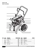
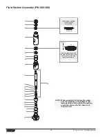
Item

Part #

Description

Quantity

1

800-325

Upper seal retainer .....................................1

2

800-327

Spacer ........................................................1

3

800-248

Upper packing assembly ............................1

4

800-351

Upper housing ............................................1

5

800-250

Lower packing assembly ............................1

6

800-354

Wear ring ....................................................1

7

800-332

O-ring, Viton................................................2

8

800-333

Back-up ring, Teflon ....................................2

9

800-352

Lower housing ............................................1

10

800-246

Piston rod....................................................1

11

800-348

Outlet valve seal .........................................1

12

800-244

Outlet valve cage........................................1

13

800-247

Outlet valve ball ..........................................1

Item

Part #

Description

Quantity

14

800-245

Washer, nylon .............................................1

15

800-243

Outlet valve seat.........................................1

16

800-336

Outlet valve retainer ...................................1

17

800-322

Foot valve cage ..........................................1

18

800-242

Foot valve ball ............................................1

19

800-241

Foot valve seat ...........................................1

20

762-058

O-ring..........................................................1

21

800-305

Foot valve housing .....................................1

22

800-365

Piston assembly (includes items 10–16) ....1

800-359

Lower packing insertion tool

800-273

Repacking kit (includes items 2, 3, 5–8, 11, 
13, 14, 18, 20, and tool)

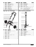
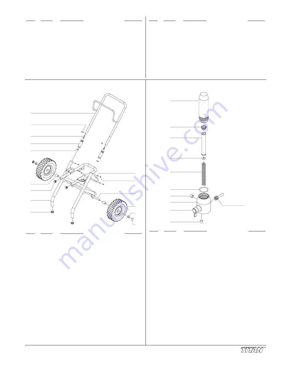
High Rider Cart (P/N 800-600)

Item

Part #

Description

Quantity

1

800-280

Handle 
(includes items 2–5, 10, and 11) ................1

2

590-508

Roll pin........................................................2

3

590-507

Snap button ................................................2

4

590-504

Sleeve.........................................................2

5

590-506

Washer........................................................2

6

800-011

Spacer ........................................................2

7

710-199

Plug.............................................................2

8

800-279

Cart (includes items 7 and 9) .....................1

9

335-018

Plug.............................................................2

10

856-002

Washer........................................................4

11

856-921

Screw..........................................................4

12

800-007

Axle.............................................................1

13

670-109

Wheel..........................................................2

14

870-004

Washer........................................................2

15

800-019

Cap .............................................................2

1

3

4

2

5

6

7

9

8

10

11

12

14

15

13

Filter Assembly (P/N 800-900)

Item

Part #

Description

Quantity

1

800-905

Filter body ...................................................1

2

800-252

Filter spring .................................................1

3

730-067

Filter, 60 mesh ............................................1

4

702-251

Filter spring adapter....................................1

5

757-105

Core spring .................................................1

6

800-906

O-ring, Teflon ..............................................1

7

800-908

Plug, 3/8” ....................................................1

8

800-901

Filter housing ..............................................1

9

800-915

PRIME/SPRAY valve assembly..................1

10

800-907

Plug, 1/4” ....................................................1

11

800-437

Transducer..................................................1

6

7

8

9

10

2

1

3

4

5

11

Содержание 800-2005

Страница 1: ...er Owner s Manual For professional use only NOTE This manual contains important warnings and instructions Please read and retain for reference NOTE This manual contains important warnings and instruct...

Страница 2: ...Refer to the PRESSURE RELIEF PRESSURE described in the pump manual ALWAYS keep tip guard in place while spraying The tip guard provides some protection but is mainly a warning device ALWAYS remove th...

Страница 3: ...uct must be grounded In the event of an electrical short circuit grounding reduces the risk of electric shock by providing an escape wire for the electric current This product is equipped with a cord...

Страница 4: ...ned out of the system with mineral spirits before you begin spraying Always keep the trigger lock on the spray gun in the locked position while preparing the system 1 Place the siphon tube into a cont...

Страница 5: ...he gun into the metal waste container until all air and solvent is flushed from the spray hose and paint is flowing freely from the gun WARNING On Off Clean Min PSI Bar Max PSI Bar S p r a y L a t e x...

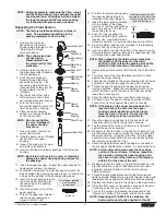
Страница 6: ...up of static electricity 5 Trigger the gun to remove any pressure that may still be in the hose 6 Lock the gun by turning the gun trigger lock to the locked position 7 Move the PRIME SPRAY valve down...

Страница 7: ...olvent WARNING CAUTION WARNING Good spray pattern Paint tailing pattern Titan Tool Inc All rights reserved 7 3 Place the siphon tube into a container of the appropriate solvent Examples of the appropr...

Страница 8: ...stem with the hole in the valve handle 7 Insert the groove pin into the valve handle and through the valve stem to secure the valve handle in position Gasket Dowel Pin Cam Base Valve Stem Filter Housi...

Страница 9: ...the four motor shroud screws Remove the motor shroud 3 Release the tie wrap on the top of the baffle assembly and slip the baffle assembly down off of the motor 4 Loosen and remove the three electroni...

Страница 10: ...Turn off and unplug the unit Before proceeding follow the Pressure Relief Procedure outlined previously in this manual Additionally follow all other warnings to reduce the risk of an injection injury...

Страница 11: ...kit over the top of the piston rod 20 Insert the piston rod into the bottom of the upper housing through the lower packing through the upper packing and out through the upper seal retainer 21 Remove...

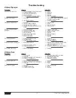
Страница 12: ...er tripped 1 Air in line 2 Insufficient pressure 1 No paint 2 Siphon strainer clogged 3 Sprayer gun filter clogged 4 Sprayer will not prime material too heavy 1 Air leak in system 2 Air leak in siphon...

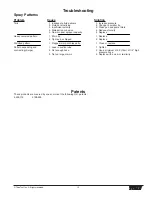
Страница 13: ...ayer capacity 1 Worn tip 2 Tip may be chipped 1 Plugged worn or chipped tip 1 Leak in suction tube 2 Not enough hose 3 Tip too large or worn Solution 1 Increase pressure 2 Change to smaller tip 3 Clea...

Страница 14: ...ntion particuli re ATTENTION AVERTISSEMENT DANGER RISQUES D EXPLOSION OU D INCENDIE Les vapeurs d gag es par le solvant ou la peinture sont explosives et inflammables et peuvent causer des corporels s...

Страница 15: ...t Ne jamais r parer un flexible d alimentation en peinture Le remplacer par un autre flexible mis la terre Tout flexible raccord orientable pistolet et accessoire utilis avec cet appareil doit pouvoir...

Страница 16: ...PARA PREVENIR Debe proveerse un escape y aire fresco para hacer que el aire que est dentro del rea de atomizaci n se mantenga libre de acumulaciones de vapores inflamables Evite todas las fuentes de i...

Страница 17: ...ierra reduce el riesgo de choque el ctrico al proporcionar un alambre de escape para la corriente el ctrica Este producto est equipado con un cable que tiene un alambre de conexi n a tierra con un enc...

Страница 18: ...551 Lock washer 2 7 858 625 Screw 2 8 800 328 Knock off nut 1 9 800 300 Fluid section assembly 1 10 451 241 Siphon tube 1 11 730 334 Hose clamp 1 Item Part Description Quantity 12 710 046 Inlet screen...

Страница 19: ...g plate 1 Item Part Description Quantity 22 800 077 Grommet 1 23 800 076 Screw 1 24 800 274 Potentiometer mounting plate 1 25 700 176 Nut 1 26 700 175 Cap 1 27 700 159 Pressure control knob 1 28 800 2...

Страница 20: ...packing with the side that has the o ring closest to the top of the packing facing up Install upper packing with raised lip facing down Raised Lip 22 Closer Top NOTE When repacking the fluid section...

Страница 21: ...des items 10 16 1 800 359 Lower packing insertion tool 800 273 Repacking kit includes items 2 3 5 8 11 13 14 18 20 and tool High Rider Cart P N 800 600 Item Part Description Quantity 1 800 280 Handle...

Страница 22: ...pacer 2 14 800 593 Wheel 2 15 800 111 Cap 2 16 800 112 Cart weldment includes items 8 and 10 1 Siphon Set low rider 1 2 3 4 5 6 Item Part Description Quantity 1 800 903 Return hose 1 2 710 203 Siphon...

Страница 23: ...t No Description 314 481 4 ounce bottle 314 480 8 ounce bottle Miscellaneous Part No Description 490 012 Hose coupling 1 4 x 1 4 730 397 High pressure fluid Gauge 314 171 Lubriplate 14 ounce individua...

Страница 24: ...tion Defective parts are to be returned to an authorized Titan sales service outlet All transportation charges including return to the factory if necessary are to be borne and prepaid by the End User...

Отзывы: