


Connecting the telephone system
27
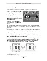
With an NFF outlet the first extension will be connected to pins 1 and 2 at the top
screwing terminal bar (using the left hand side N coded and the centre F coded jack)
and the second extension will be connected to pins 1 and 2 of the lower screwing
terminal bar (using the right hand F coded jack).
Note:
In other countries instead of TAE type outlets other standards are being
used for wall outlets.
Connection by using network installation cable
In case there is a network infrastructure with patch panel and network outlets close to
the telephone system you can also use this wiring for connecting analogue tele-
phones.
Connect the RJ-11 jack of your telephone system to the patch panel and connect the
analogue telephone to the network outlet in the corresponding room. For both instal-
lations you need a cable with a 4 pin RJ-11 plug at one end and an 8 pin RJ-45 plug
at the other end. Your specialist dealer will provide you with such cables.
To integrate extension 5 - 8 in you patch panel wiring below the telephone system
you should install a UAE (Universal Anschluss Einheit-) wall outlet. Connect the two
wires of an analogue extension at the screwing terminal bar at your telephone system
by using an installation cable with terminals 4 and 5 of the UAE outlet. Now you can
connect the jack of the UAE outlet with the jack on the patch panel.
Note:
By using the circuit as explained above the two centre wires of the
patch cable and thus, also at the telephone are being used. This is cor-
rect with most telephones. A few telephones, however, do not use the
centre wires but instead are using the wires right next to those wires to
the left and the right. If this is the case with your analogue telephone
you must use terminals 3 and 6 of your UAE outlet instead of 4 and 5.


