


B. INTEGRAL PARTS AND FUNCTIONALITY
B-7
BeFREE 20 – TECHNICAL OVERVIEW
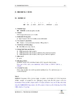
B.5.
External Connectors
Numerous connections for external devices are available at the Connector Plate (see
Figure B.5) from underneath the module. Most of them are standard interfaces (USB,
LAN, COM, VGA …) intended for users to apply freely.
#
Designator
Type
Note
1
12V Input
Mini Power DIN
reserved
2
Digital Input
RJ 4P/4C socket
see Chapter B.5.1
3
Dual USB
2 × USB type – A
full-speed, 500 mA
4
Dual USB
2 × USB type – A
full-speed, 500 mA
5
Dual USB
2 × USB type – A
high-speed, 500 mA
6
LAN 1
RJ 8P/8C (RJ 45)
1 Gb Ethernet
7
LAN 2
RJ 8P/8C (RJ 45)
1 Gb Ethernet
8
COM 1
DSUB-9 male
RS232 serial port
9
VGA
DSUB-15 female
analogue RGB output
Figure B.5 Connector Plate
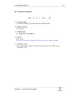
B.5.1.
External Digital Inputs
Two inputs (refer to Figure B.6 for the connector and signal description) are provided
for detection of external digital (ON/OFF) signals to be transformed into programmable
key events, equivalent to, for instance, PushToTalk key on the Stripe. Typical device to be
connected to is an external PushToTalk switch/pedal.
One of the inputs (A) is galvanically isolated (via opto-coupler) and is therefore
intended for an external ground-referenced signal, such as a digital output of another
electronic device. The other input (B) is to be used for an external “floating” signal, such
as contacts of a mechanical/magnetic key/switch (see Figure B.7).
1
1
3
3
4
4
5
5
6
6
7
7
8
8
9
9
2
2


