Web: www.tinker-rasor.com
E-mail: [email protected]
Page
4
of
6
CORROSION
MITIGATION
INSTRUMENTATION
P.
O.
B
OX
1667
S
AN
B
ERNARDINO
,
C
A
92402
T
EL
:
(909)
890-0700
F
AX
:
(909)
890-0736
P
RODUCT
I
NSTRUCTIONS
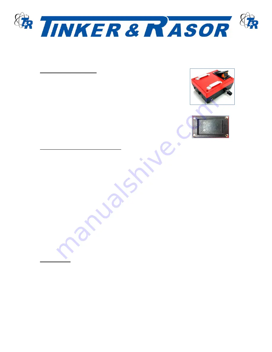
CHANGING THE BATTERY
The M/1 is powered by a replaceable 9v battery. To access the battery,
locate the battery holder on the back of the Red case. See Figure 2. Use a
fingernail or small flat head screwdriver to open the battery holder and
rotate up away from the case.
Remove the old battery and replace with the new battery. When replacing
the battery, observe polarity. See Figure 3. The 9v battery has two
terminals side by side. The smaller terminal is the Positive (+) connection,
as indicated on the battery (most batteries). The larger terminal on the
battery is Negative (-). When connecting the 9v battery to the battery
connector, ensure that the terminals are mating with the corresponding
connector. If the battery holder does not close easily the battery may be in
backwards.
ELECTRICAL TESTING PROCEDURES
The sponge electrode should contain sufficient amount of wetting solution to assure moisture
penetration from the sponge electrode into any defect that may be present in the protective coating.
Excess wetting solution should be squeezed out of the sponge electrode.
Attach ground wire directly to the bare structure (substrate) under test. On coated steel structures
the ground wire must be directly connected to the bare metal.
On coated concrete structures the ground wire should be connected directly to the reinforcing steel
embedded in the concrete. If rebar is not present, a ground connection to the concrete can be
made by placing the bare end of the ground wire against the bare concrete surface and anchor it
down with a burlap bag filled with damp sand.
The ground wire can be checked quickly for proper connection by contacting the wetted sponge
electrode to the bare structure and observing an audible signal, indicating correct electrical
continuity of the holiday detector circuit.
The rate of inspection speed of the sponge electrode over the protective coated surface should not
exceed sixty (60) linear feet per minute. Using a double stroke of the sponge electrode over each
area assures better inspection coverage with less likelihood of any missed areas.
CALIBRATION
Factory calibration on Model M/1 Holiday Detectors is set at 700 micro-amperes (+/- 10%) of current
flow to complete the circuit for the audible signal to indicate a coating holiday on metal substrates.
For coatings on concrete substrates, the Model M/1 must be adjusted for current flow of 500 micro-
amperes (+/- 10%).
Figure 2
Figure 3


