TIFFIN MOTORHOMES
–ALLEGRO BUS®
Chapter 7
ELECTRICAL FEATURES
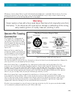
unlocked before free movement is possible. There is a “pull” cable (Figure 7-18) in the
external compartment in front of the front tire on the driver’s side—pulling this cable
will release the slide lock for the generator.
Prior to starting or stopping the generator, make sure that all the 120 VAC appliances
are turned “off.” After the generator has been started, wait until the transfer switch
has connected before turning “on” any of the appliances.
The generator can be started from either the remote-start switch located on the dash
or directly at the generator itself. The hour meter installed on the generator records
the number of hours of operation of the generator motor—this elapsed time is needed
for observing necessary maintenance schedules on the generator.
7-13
For more detailed operating instructions of the generator and to determine necessary preventive-maintenance
schedules and procedures, review the manufacturer owner’s manual.
Automatic Transfer Switch
The automatic transfer box switches AC power from shore to generator to the coach main distribution panel. This is
achieved by the closing and opening of contactors that are located in the box interior (see diagram on Automatic
Transfer Switch which is located in owner’s information package). Power from shore is fed through contacts located on
R4 and R5. Power input is sensed by electrical board B1. If shoreline neutral is present it will allow relay R1 to energize
which energizes relays R2 and R3 applying shore power to the main control box located in the motor home. If the unit
senses that an open neutral condition exists, R1 will not energize not allowing the coach to receive the potentially
appliance damaging voltage. Power from the generator is sensed by boar d B1 and after a delay of 15-20 seconds, R4
and R5 energize automatically disconnecting shore power B1 checks for generator neutral and if present allow R2 and
R3 to energize allowing generator power to the main control panel.
Figure 7-18. “Pull” Cable for
Generator Release
Caution
Failure to turn “off” the 120 VAC appliances when
starting or stopping the generator
may damage the transfer switch and/or electrical
appliances.
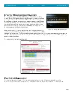
Figure 7-17. Electrical Generator
Содержание 2014 Allegro Bus
Страница 6: ... TIFFIN MOTORHOMES ALLEGRO BUS Chapter 1 GENERAL INFORMATION GENERAL INFORMATION 1 1 ...
Страница 13: ... TIFFIN MOTORHOMES ALLEGRO BUS Chapter 1 DRIVING SAFETY INSTRUCTIONS DRIVING SAFETY INSTRUCTIONS 2 1 ...
Страница 24: ... TIFFIN MOTORHOMES ALLEGRO BUS Chapter 3 HEATING AIR CONDITIONING HEATING AIR CONDITIONING 2 1 ...
Страница 33: ... TIFFIN MOTORHOMES ALLEGRO BUS Chapter 4 MAJOR APPLIANCES ACCESSORIES MAJOR APPLIANCES ACCESSORIES 4 1 ...
Страница 51: ... TIFFIN MOTORHOMES ALLEGRO BUS Chapter 5 CABINETS FURNITURE CABINETS FURNITURE 5 1 ...
Страница 55: ... TIFFIN MOTORHOMES ALLEGRO BUS Chapter 6 STRUCTURAL FEATURES STRUCTURAL FEATURES 6 1 ...
Страница 57: ... TIFFIN MOTORHOMES ALLEGRO BUS Chapter 7 ELECTRICAL FEATURES ELECTRICAL FEATURES 7 1 ...
Страница 72: ... TIFFIN MOTORHOMES ALLEGRO BUS Chapter 8 SLIDE OUT FEATURES SLIDE OUT FEATURES 8 1 ...
Страница 76: ... TIFFIN MOTORHOMES ALLEGRO BUS Chapter 9 EXTERIOR FEATURES EXTERIOR FEATURES 9 1 ...
Страница 83: ... TIFFIN MOTORHOMES ALLEGRO BUS Chapter 10 INTERIOR FEATURES INTERIOR FEATURES 10 1 ...
Страница 87: ... TIFFIN MOTORHOMES ALLEGRO BUS Chapter 11 PLUMBING BATH FIXTURES PLUMBING BATH FIXTURES 11 1 ...
Страница 100: ... TIFFIN MOTORHOMES ALLEGRO BUS Chapter 12 WINDOWS AWNINGS VENTS DOORS WINDOWS AWNINGS VENTS DOORS 12 1 ...
Страница 105: ... TIFFIN MOTORHOMES ALLEGRO BUS Chapter 13 ROUTINE MAINTENANCE ROUTINE MAINTENANCE 13 1 ...
Страница 143: ... TIFFIN MOTORHOMES ALLEGRO BUS Chapter 14 MAINTENANCE DATA CHARTS MAINTENANCE DATA CHARTS 14 1 ...


