background image


Chapter 7 

Technical Specifications and Port Information 

7


Input frequency range: 

11.7 to 12.2 GHz 
12.25 to 12.75 GHz 
10.95 to 11.7 GHz 
3.7 to 4.2 GHz 

Output frequency range:  

950 to 1450 MHz 
950 to 1700 MHz 

Conversion gain: 

55 to 70 dB 

LNB Downconverter (Outdoor 
Unit - ODU) 

Local oscillator: 

DRO (BPSK) or PLL (QPSK) 

Input frequency range: 

950 to 1700 MHz, F connector, 75 ohm 

Output power (to LNB): 

+13,14,18,19 VDC, 750 mA maximum 
current – or OFF 

Input signal level: 

-75 to -20 dBm 

Frequency step size: 

1 kHz steps 

Demodulation type: 

BPSK or QPSK 

FEC decoding: 

Sequential rate ½ and 3/4 
DVB-Viterbi rate 1/2, 2/3, ¾, 5/6 and 7/8; or 
concatenated Viterbi and Reed Solomon rate 
187/204 and 188/204 

BER performance: 

128 kbps (BPSK) 1x10⁻⁵ at 4.0 dB Eb/No, 
Sequential rate ½ 
128 kbps (QPSK) 1x10⁻⁵ at 4.5 dB Eb/No, 
Sequential rate ½ 
Max Eb/No for BER < 1e-10 after RS: Vit 1/2 
= 4.5 dB, Vit 2/3 = 5.0 dB, Vit 3/4 = 5.5 dB, 
Vit 5/6 = 6.0 dB, Vit 7/8 = 6.4 dB 

Data Rates: 

32 – 448 kbps variable in 1 bps increments 

L-band Demodulator  
(Indoor Unit - IDU) 


Symbol rates: 

64 - 256 ksps 


Size: 

1.75" H x 17.375" W x 15.75" D 
(1 RU 19" rack-mount) 

Unit weight: 

6 lbs 

Shipping weight: 

12 lbs 

Power


Input voltage (AC):


90 to 264 VAC 

Frequency: 

47 to 63 Hz 

Consumption: 

< 20 W typical 

Mechanical (IDU) 

Environmental


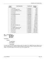
Tiernan DBR3000 


Page 

7-1


Содержание DBR3000

Страница 1: ...Installation and Operation Guide For The Tiernan DBR3000 Digital Broadcast Receiver 01 2002 401 Revision B ...

Страница 2: ...Overview Page 1 2 Tiernan DBR3000 ...

Страница 3: ...nit The original factory shipping carton and packing materials were specifically designed to protect Tiernan equipment from excessive shock and vibrations Please use the original shipping carton and packing materials to ship your Tiernan equipment Shipping Addresses For Domestic Shipments Within the United States Tiernan A Radyne Company Customer Service 7330 Trade Street San Diego CA 92121 RMA Fo...

Страница 4: ...Shipments Tiernan A Radyne Company does not accept responsibility for units that are improperly packaged or damaged in shipment and may reject such shipments Tiernan A Radyne Company will reject shipments Without an RMA number Shipped as Freight Collect If the original product identification markings or labels have been removed defaced or altered Customer Service 24 Hours a Day 7 Days a Week We kn...

Страница 5: ...ce quotation Expired Warranty If the warranty on your product has expired the Administrator will fax you a Product Repair Quote This quote must be approved and returned to the Customer Service Administrator along with a valid purchase order PO before an RMA number can be issued Online Assistance E mail Us To contact Customer Service via e mail send a message to customerservice radn com Tiernan on ...

Страница 6: ...Warranty Policy Page vi Tiernan DBR3000 ...

Страница 7: ...as RESET ALARMS while a command that calls for the entry of a 7 followed by ENTER Key will be represented as 7 ENTER Notes Cautions and Warnings A note icon identifies information for the proper operation of your equipment including helpful hints shortcuts or important reminders A caution icon indicates a hazardous situation that if not avoided may result in minor or moderate injury Caution may al...

Страница 8: ...o this Manual The most up to date copy of this manual can be downloaded from our web site located at http www tiernan com As of the present date Technical Manuals for Tiernan products are available in PDF format at http www tiernan com Notice This publication and its contents are proprietary to Tiernan a Radyne Company and are intended solely for the contractual use of its customers for no other p...

Страница 9: ...n of liability for incidental or consequential damages so the above limitation or exclusion may not apply to you For further information on legal and intellectual property matters contact Tiernan a Radyne Company This equipment has been tested and found to comply with the limits for a Class A digital device pursuant to part 15 of the FCC Rules These limits are designed to provide reasonable protec...

Страница 10: ...Preface Page x Tiernan DBR3000 ...

Страница 11: ...ir circulation If the equipment is placed in a closed area such as a rack ensure that proper ventilation is provided and that the internal rack operating temperature does not exceed the maximum rated temperature at the position of the unit Never place the unit on a soft surface that would obstruct the required airflow into the ventilation slots Use Correct Power Source For units equipped with a No...

Страница 12: ...o not place or stack any objects on top of the unit Other equipment may be placed in a rack or on a shelf above or below the unit but never stacked directly on top of it Protect Against Lightning and Power Surges When the unit is installed have the professional installer ground the system to protect against voltage surges and built up static charges For information on grounding standards for elect...

Страница 13: ...couring powders aerosol cleaners or solvents such as alcohol or benzene Use only a clean soft cloth lightly moistened with a mild detergent solution Wipe all equipment with a clean soft cloth lightly moistened with water to remove the detergent solution Service the Unit Do not attempt to service the unit yourself as there are no user serviceable parts Opening or removing covers may expose you to d...

Страница 14: ...Safety Precautions Page xiv Tiernan DBR3000 ...

Страница 15: ...10 2 1 4 DBR Satellite Receiver 2 11 2 1 5 Using the Front Panel 2 11 2 2 Theory of Operation 2 12 2 2 1 Satellite Link 2 13 2 3 DBR Carrier Acquisition 2 15 2 3 1 Installation Mode Acquisition 2 15 2 3 2 Fade Acquisition 2 16 Chapter 3 Quick Installation 3 1 3 1 Overview 3 1 3 2 Quick Installation Procedure 3 1 Chapter 4 Full Installation and Startup 4 3 4 1 Overview 4 3 4 2 Installation Overview...

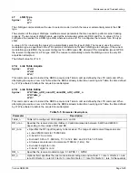
Страница 16: ...Syntax 5 13 5 3 Password Protection 5 14 5 4 Command Error Codes 5 14 5 5 Command Groups 5 14 5 6 Command Descriptions 5 16 Chapter 6 Maintenance and Troubleshooting 6 29 6 1 Maintenance 6 29 6 2 Performance Monitoring 6 29 6 2 1 Eb No Minimum Receive Level EM 6 29 6 2 2 Number of RF Signal Fades NF 6 29 6 3 Fault Condition Descriptions 6 30 6 4 Troubleshooting 6 31 6 4 1 Before Troubleshooting 6 ...

Страница 17: ...etwork 1 6 Figure 2 1 Receive Only Antenna Assembly 2 9 Figure 2 2 LNB Downconverter PLL Block Diagram 2 10 Figure 2 3 DBR Unit 2 11 Figure 2 4 Installation Acquisition Mode 2 16 Figure 2 5 Fade Acquisition Mode 2 16 Figure 4 1 Rear Panel Connectors 4 5 Tiernan DBR3000 Page 1 3 ...

Страница 18: ...s vs Data Rate 4 4 Table 4 2 Certifying Agencies by Country 4 9 Table 5 1 Error Codes Descriptions 5 14 Table 5 2 Alphabetical Command Listing 5 14 Table 5 3 Acquisition Type Action Status 5 17 Table 5 4 Fault Summary 5 20 Table 5 5 Parameter Descriptions 5 23 Table 5 6 Valid Parameter Values for the P2 Command 5 25 Table 5 7 Signal Strength LED Indication 5 27 1 4 Tiernan DBR3000 ...

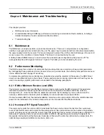
Страница 19: ...stantaneous such communication is ideal for time intensive applications The DBR3000 Digital Broadcast Receiver is an extremely reliable powerful and easy to use system that enables you to take advantage of these and many other benefits of satellite communications This chapter provides an overview of a typical satellite distribution network as well as an overview of the DBR3000 Digital Broadcast Re...

Страница 20: ...band and Ku band The third major subsystem the remote satellite receiver includes three major components A satellite antenna subsystem An interfacility link cable A satellite data receiver such as the DBR The satellite antenna and its associated Low Noise Block LNB downconverter collect and convert the signal from the satellite s native C or Ku band signal to L band A phase lock loop PLL type LNB ...

Страница 21: ...s are not lost in the event of a power outage and event logs specify time Provides a 10 100BASE T Fast Ethernet port running a Telnet server for monitor and control from any computer or other device containing an Ethernet port and Telnet client software Provides a front panel interface that allows for quick monitoring The remaining portion of this manual describes in detail the steps necessary to ...

Страница 22: ...cies A user supplied interfacility link IFL cable connecting the LNB downconverter on the antenna to the DBR A DBR receiver providing an L band demodulator 2 1 Functional Description 2 1 1 Outdoor Components The outdoor components consist of an antenna assembly a feed assembly and an LNB downconverter 2 1 1 1 Antenna Assembly The antenna assembly consists of the satellite reflector mast feed horn ...

Страница 23: ...all mount 2 4 m linear or cicular 90 m AZ EL mount 3 0 m linear or cicular 1 0 m AZ EL mount 3 4 m linear or cicular 1 2 m AZ EL mount 3 7 m linear or cicular also polar mount 1 8 m AZ EL mount1 2 4 m AZ EL mount1 3 0 m AZ EL mount1 3 4 m AZ EL mount1 3 7 m AZ EL mount1 1 Available in both single and dual feed The antenna subsystem receives DC power from the DBR receiver via the IFL cable so an ad...

Страница 24: ... amplifier LNA A dielectric resonance oscillator DRO or phase lock loop PLL oscillator A mixer An image reject filter An IF amplifier The input of the LNB downconverter receives signals collected by the antenna and routes them to the LNA The LNA sets the LNB downconverter noise figure and provides the first stage of amplification The amplified signal is mixed with the local oscillator for downconv...

Страница 25: ...e following LED indicators 2 1 5 1 Front Panel Indicators Table 2 2 Front Panel Indicators Indicator Color Description Power Green Indicates the unit is powered on and changes color based on the presence of any operating fault If the Power LED is green the unit is powered on If the Power LED is off then the power supply is not functioning properly Refer to the Troubleshooting section to determine ...

Страница 26: ...n The DBR operates in three FEC modes Sequential o Rates 1 2 and 3 4 ComStream Viterbi o Rates Intelsat 1 2 DVB 1 2 DVB 2 3 DVB 3 4 DVB 5 6 and DVB 7 8 Viterbi and Reed Solomon Non DVB 187 204 rate DVB 188 204 rate Sequential and Viterbi modes are closed network modes When operating in concatenated Viterbi and Reed Solomon FEC the DBR offers two discrete operating modes DVB and non DVB Non DVB mod...

Страница 27: ...and instructing the DBR to switch to the second link table and then if required issuing another command to cause the DBR to switch back to the first link table Automatically lock onto either link table Automatic use of the two link tables occurs when both link tables are enabled for acquisition An additional feature of the link tables is a special wait time that instructs the DBR to spend a specif...

Страница 28: ...pspeed Sequence Time 7 The DBR is instructed to enable both link tables for acquisition Time 8 The DBR is instructed to acquire based on Link Table B The hub continues to operate at 128 kbps and at the same RF downlink frequency Time 9 The DBR reacquires using Link Table A after finding no operational link with Link Table B Successful Upspeed Sequence Time 10 The DBR is instructed to use a link ta...

Страница 29: ...tion begins at the nominal carrier center frequency which is user defined by the Link Table Define LTD command and the acquisition offset AO command An attempt to acquire the carrier begins by searching a range of frequencies called a frequency bin centered around the nominal carrier frequency The size of this range is determined by the symbol rate If the DBR is unable to find the carrier within t...

Страница 30: ...search continues in the areas above and below sequentially The size of the range searched outside the B1 range is defined by the B2 command These points are indicated in Figure 2 5 as B21 and B22 Once the B21 and B22 ranges are searched the receiver returns to P0 and resumes the expanding search from the beginning When the B1 limit is reached again the system searches another B2 range beyond the l...

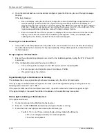
Страница 31: ...em startup is straightforward If the above conditions do not apply or if you experience problems following the Quick Installation procedure refer to the chapter on Full Installation and Startup To perform quick installation 1 Make sure the DBR is properly installed in an equipment rack or on a flat surface with the following connected AC cord IFL cable Data port cable Ensure that the unit has at l...

Страница 32: ...econds MR 0 to select a DRO LNB MR 1 to select a PLL LNB Enable the LNB DC voltage as necessary LV 3 Selects 18VDC Enter the Link Table Definition Command format is LTD table data_rate rf_frequency modulation_type coding_rate outer_block_code_rate ibs Select the link table to acquire Command format is LTA table Initiate initial acquisition search mode by entering AQ 2 3 Observe the following about...

Страница 33: ...ts Time spent in planning prevents unnecessary complications during installation and allows potential problems to be resolved before work begins There are three main issues to be addressed Location and mounting of the antenna assembly Routing of the IFL cable Location of the DBR 4 4 Installing and Aligning the Antenna The location of the receiving antenna is the first element to be considered The ...

Страница 34: ...able run using an adequate antenna or installing a line amplifier with a gain of 20 to 30 dB such as the LA 20 by Norsat 604 597 6278 Ensure that the line amplifier also passes the LNB DC line voltage on to the LNB downconverter Table 4 1 provides information on maximum cable losses that are acceptable before signal degradation can be expected assuming 5 dB Eb No LNB output 55 dB LNB gain 150 K sy...

Страница 35: ...re many surge suppression vendors that can recommend and supply products to meet your voltage and power requirements In addition placement of the DBR should allow access to its rear panel The IDU should be rack mounted only in enclosures that will not exceed an ambient temperature of 50 C 4 7 External Connections This section describes the physical and electrical connections to the DBR receiver En...

Страница 36: ... the Status Relay is its ability to be programmed to trigger when specific user selected fault conditions are detected while ignoring others This allows the status relay actions to be customized for the conditions at a specific receiver installation The status relay mask SR command provides this customizing ability For specific details refer to the chapter on Remote Monitor and Control Operation B...

Страница 37: ...00 bps 7 data bits odd parity and 1 stop bit The M C port will also accept commands via an RS 485 party line bus While the receiver does not distinguish between RS 232 and RS 485 electrical levels it is essential to invoke packet only mode for multiple Tiernan products communicating over the same RS 485 bus in Tiernan ComStream Packet Protocol The DBR is a slave on the RS 485 bus i e it only respo...

Страница 38: ...er supply output for the DBR is 60 watts The typical power consumption for the DBR is less than 20 watts There is no power on off switch on the receiver Remove the AC power cable from the unit to turn the power off Always power down the DBR before connecting or disconnecting signal cables to the unit If an unterminated power cord is supplied with the unit the appropriate certified termination plug...

Страница 39: ...KEMA New Zealand SECV SECQ SECWA EANSW ETSA HECT SANZ Norway NEMKO Republic of So Africa SABS Spain AEE Sweden SEMKO Switzerland SEV United Kingdom ASTA BSI 4 8 Starting Up the System This section describes the activities necessary to bring an assembled DBR system online The following steps assume that the antenna IFL cable and DBR have been properly installed and connected Do not proceed until th...

Страница 40: ...DBR is ready for verifying proper equipment setup and operation Validating Installation Once the DBR has been powered up verify that the unit is connected properly This is accomplished by communicating with the receiver using an ASCII terminal and performing several diagnostic commands The electrical interface is RS 232 on a PC AT style DB 9 connector DTE presentation The terminal should be config...

Страница 41: ...ise requested Use of a DRO LNB requires that a master reset MR command be invoked first with the applicable argument shown below MR 0 to select a DRO LNB MR 1 to select a PLL LNB Enable the LNB DC voltage as necessary LV 3 Selects 18VDC Enter the Link Table Definition Command format is LTD table data_rate rf_frequency modulation_type coding_rate outer_block_code_rate ibs Select the link table to a...

Страница 42: ...ectly and the signal is present AG other than 255 but the unit will not acquire then there could be many possible causes Enter DP on the diagnostic terminal Check the values of B1 B2 and B3 If operating in QPSK mode then spectral inversions caused by a high side local oscillator in the transmission chain may also prevent lock Set the DI parameter to compensate for spectral inversion if necessary C...

Страница 43: ...Most commands are used to establish internal parameter values and interrogate their current value The parameter may be either a single digit number referenced as n a multiple digit number referenced as nnnnn or a single ASCII character or string designated s or string Syntax that appears in italics represents variable characters this syntax varies depending on what information is being requested P...

Страница 44: ...mand not supported by configuration ER 4 Command temporarily not supported 5 5 Command Groups Most commands establish the operating characteristics of the receiver These commands install permanent values into memory that remain in place unless changed by the operator Operators should avoid changing configuration values unless they are certain of the result Most of the operating parameters are esta...

Страница 45: ...eive Level FL Fault Query FM Event and Fault Manager HM Hex Mode ID Receiver ID Query IP IP Address LA Logical Address Definition LO Local Oscillator Offset LT LNB Type LTA Link Table Acquire LTD Link Table Define LTE Link Table Enable LTW Link Table Wait LV LNB Voltage MR Master Reset NF Number of RF Signal Fades P2 M C Port Configuration PA Packet Address PC Password Change PE Password Enable PO...

Страница 46: ...trols the value of the acquisition offset The acquisition offset is used to optimize the power on acquisition process The acquisition offset value is used by the DBR in its calculations for the frequency at which it will begin its search for the RF carrier on a power on acquisition The value of AO is automatically updated to the local offset LO value if the LO value is ever greater than 50 kHz On ...

Страница 47: ...ow the B1 range After the search of a B2 range the B1 range is searched again When all B2 ranges have been searched within the user specified acquisition range limit B3 without finding the carrier the search pattern is repeated from the beginning A detailed description of the DBR acquisition process can be found in the chapter on Functional Description and Theory of Operation B2 Secondary Search B...

Страница 48: ...gister The FL and ST command descriptions contain a complete list of all fault code bit numbers DATE Date Syntax DATE month_nn date_nn year_nnnn DATE This command allows the user to enter the current date of the real time clock The valid range for month_nn is 1 to 12 The valid range of date_nn is 1 to 31 The valid range of year_nnnn is 2000 to 2199 DC Display Configuration of Receiver Syntax DC DC...

Страница 49: ... No is returned in the range of 3 dB to 20 dB The Eb No value is in 0 1 dB steps with an accuracy of 0 5 dB in the range between 4 0 and 10 dB This value is valid approximately 20 seconds after DBR acquisition and is updated every five seconds The maximum Eb No value for all Viterbi rates is 11 5 dB EE Echo Terminal Input Syntax EE n EE This command specifies whether characters input to the M C po...

Страница 50: ...ar fault indication The fault status map is shown in Table 5 23 The bits in the fault register are identical to those in the status register For more information refer to the ST command section in this chapter If the hex mode HM is enabled 1 then the output is displayed in the hexadecimal format given in Table 5 23 with all bits displayed that are set If the hex mode is disabled default then the o...

Страница 51: ... used 0x00800000 8388608 25 Eb No Threshold Fault 0x01000000 16777216 26 Not used 0x02000000 33554432 27 EPROM Checksum Fault 0x04000000 67108864 28 S W Download Failure 0x08000000 134217728 29 Not used 0x10000000 268435456 30 Not used 0x20000000 536870912 31 Not used 0x40000000 1073741824 FM Event Manager Syntax FM CURRENT FM HISTORY FM CLEAR Front Panel Events Current Events Event History Clear ...

Страница 52: ...that an IP Address of 0 0 0 0 disables the Ethernet port LA Logical Address Definition Syntax LA nn address_nnnnn LA LA This command allows the receiver to respond to logical addresses received over the network control channel Up to 32 logical addresses can be assigned to each receiver The valid range for address_nnnnn is 1 to 16383 An individual 0 for the address clears the logical address assign...

Страница 53: ... new Link Table when the DBR is already locked to an existing Link Table the time defined by LTW is adhered to before the acquisition is attempted LTD Link Table Define Syntax LTD Table_n DR_nnnn RF_nnnn RM_n RC_n RSC_n LTD Table_n LTD This command is used to instruct the DBR to acquire Link Table A or B as defined by the LTD command When attempting to acquire a new Link Table when the DBR is alre...

Страница 54: ...re beginning to ping pong After this wait time has expired the acquisition algorithm resumes trying each link table one directly after the other without any further delay time The wait time is only applied one time in an LTA acquisition The purpose of LTW is to allow the DBR to concentrate on the link table specified by LTA for a period of time If after that time period there has been no successfu...

Страница 55: ... Number of RF Signal Fades Syntax NF NF NF 0 This command displays the number of RF signal fades since the counter was last cleared NF 0 resets the counter P2 M C Port Configuration Syntax P2 baud parity data bits stop bits P2 This command configures the diagnostic port for the specified parameters Valid values for these parameters are shown in Table 5 29 Table 5 6 Valid Parameter Values for the P...

Страница 56: ...ng PC HOMEYD ABC123 ABC123 Do not forget that changes made to the password upon logoff or power cycle require the entry of the password to access any other user commands PE Password Enable Syntax PA n PA This command is used to enable or disable the password protection on the M C port of the receiver When n is 0 the password protection is disabled and when n is 1 password protection is enabled PO ...

Страница 57: ... measured Eb N0 with the user values of Q0 and Q1 The receiver displays the signal strength via the front panel Signal indicator as shown in Table 5 32 Table 5 7 Signal Strength LED Indication Signal Strength LED Indication Eb Q1 On Q0 Eb Q1 Blinking Eb Q0 Off The default value for Q0 is 4 0 dB Q1 High Signal Quality Threshold Level Syntax Q1 n n Q1 Q1 This command sets or reads the upper limit si...

Страница 58: ...relay For example to set faults 6 7 and 8 you would input 224 32 64 128 as the value of nnnn For a listing of fault monitors and their decimal weighting refer to the FL command The default value is 4286578687 which enables all faults but FL 24 to activate the relay and front panel IDU Fault indicator ST Status Query Syntax ST ST This command causes the receiver to display the current content of th...

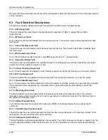
Страница 59: ...At these sites the DBR Telnet server can be utilized to login to the console The key performance monitoring commands and how they can be used in measuring symptom performance are detailed in the following paragraphs 6 2 1 Eb No Minimum Receive Level EM The minimum receive signal level Eb No is measured and recorded using the EM command This parameter indicates how weak the receive signal has becom...

Страница 60: ...egister has reached its maximum or minimum setting FL12 Bit Time Range Fault This fault indicates the demodulator bit time accumulator has reached its maximum or minimum setting FL 13 Nonvolatile Memory Fault An FL 13 fault means one of the parameters in the demodulator nonvolatile memory may have become corrupted If this indication occurs repeatedly the nonvolatile memory is defective and the uni...

Страница 61: ...e power has not been turned off there are no loose cables or any damaged connectors Is the receiver located at the uplink or is it a downlink in a network If it is a downlink are other downlinks experiencing any problems 6 4 2 Symptoms and Actions This section has been developed to help you diagnose and correct minor problems in the unlikely event that you experience difficulties with your DBR Pow...

Страница 62: ...echnical support Rx Sync light is not illuminated 1 Ensure the configuration parameters are correct for the installed application using the LTD LTA and DI commands 2 If the configuration parameters have been confirmed Connect the spectrum analyzer to the LNB output via a DC coupled splitter Ensure a proper L band signal is present and above 75dBm If required repeak the antenna Signal Quality light...

Страница 63: ...Maintenance and Troubleshooting If the above faults are present verify carrier status and configuration before contacting Tiernan for technical support Tiernan DBR3000 Page 6 33 ...

Страница 64: ......

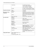
Страница 65: ... QPSK FEC decoding Sequential rate and 3 4 DVB Viterbi rate 1 2 2 3 5 6 and 7 8 or concatenated Viterbi and Reed Solomon rate 187 204 and 188 204 BER performance 128 kbps BPSK 1x10 5 at 4 0 dB Eb No Sequential rate 128 kbps QPSK 1x10 5 at 4 5 dB Eb No Sequential rate Max Eb No for BER 1e 10 after RS Vit 1 2 4 5 dB Vit 2 3 5 0 dB Vit 3 4 5 5 dB Vit 5 6 6 0 dB Vit 7 8 6 4 dB Data Rates 32 448 kbps v...

Страница 66: ...onitor and Control Capabilities Status Front Panel Power RF Sync Fault summary Aux Port Connector DB 15 female Functions Receiver fault alarm relay Form A Synchronous RS 422 Data Port Interface type Synchronous RS 422 Connector DB 25 female M C Port Interface type Asynchronous RS 232 and addressable RS 485 multidrop using Tiernan ComStream s packet protocol Connector DB 9 female with DTR control D...

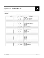
Страница 67: ... Not Used 5 Not Used 6 O DSR Data Set Ready Reserved 7 Not Used 8 Not Used 9 O AUXRT RT Clock RS 422 10 Not Used 11 O AUXRD Rcv Data RS 422 12 Not Used 13 O SG Signal Ground 14 Not Used 15 Not Used 16 Not Used 17 Not Used 18 Not Used 19 Not Used 20 Not Used 21 Not Used 22 O AUXRT RT Clock RS 422 23 Not Used 24 O AUXRD Rcv Data RS 422 25 Not Used Tiernan DBR3000 Page A 1 ...

Страница 68: ...tus Closure Contact Closed on Fault 2 O StatusNO Status Closure Contact Open on Fault 3 I BBRD BB Rec Data RS 422 Reserved 4 O RD Receive Data RS 422 A 5 Not Used 6 O RT Receive Timing RS 422 A 7 I BBRT BB Rec Timing RS 422 Reserved 8 O SG Signal Ground 9 O StatusCOM Status Closure Common 10 I BBRD BB Rec Data RS 422 Reserved 11 O RD Receive Data RS 422 B 12 I M C Reset Monitor and Control Port Re...

Страница 69: ...ghtly and evenly in a manner consistent with the physical mechanical environmental and dimensional requirements The outer jacket material should be weatherproof and suitable for direct burial A flooding compound must be applied to the outer braid under the jacket of the coaxial cable to block moisture and resist corrosion Polyisobutylene is the recommended flooding compound Polyvinyl chloride Ther...

Страница 70: ...one Manufacturer Part Number F male connector Gilbert Engineering 800 528 5567 GAF 11 AHS 480 Crimp Tool Gilbert Engineering 800 528 5567 GCRT 211 Cable type is determined by the amount of maximum signal loss specified in Table C 3 Table C 3 Signal Loss per 100 Foot Length for Common Cable Types Cable Type Loss Per 100 Feet RG 11 preferred 5 9 dB RG 35 3 7 dB Generally an IFL cable run of 0 to 420...

Страница 71: ...d here and as illustrated in Figure C 1 1 Remove 3 4 inch 9 55 mm of the cable jacket being careful not to cut through the braid Fold the first layer of exposed braid back over the jacket 2 Cut through the remaining foil braid and dielectric to expose 1 4 inch of center conductor Do not score the center conductor 3 Remove the first foil making sure the braid is not cut and fold the second braid ov...

Страница 72: ...d Loop the cable in such a way that the length of the cable between the LNB downconverter and the tie wrap nearest it is approximately 10 inches 5 Add additional tie wraps along the lower feed rod at the middle and bottom as required to secure the IFL cable Page B 4 Tiernan DBR3000 ...

Страница 73: ...Troubleshooting Figure C 1 Coax Cable and F Connector Assembly Tiernan DBR3000 Page B 5 ...

Страница 74: ...Troubleshooting Page B 6 Tiernan DBR3000 ...

Отзывы: